Cracked
April 6, 2011 at 12:50 PM by Dr. Drang
Hey, there’s something in the news that I actually know a good deal about! The roof failure on Southwest Flight 812 is being blamed on fatigue, which is the fracture of a part under repeated loadings.
Fatigue is one of those words, like stress and strain, that engineers have appropriated from everyday use and given a technical definition. In this case, the appropriation is apt. Imagine that you’ve been assigned to pick up a 25-pound load and put it on a shelf. Easy, right? Now imagine doing that once or twice a minute throughout the course of a day. It’s easy to see yourself getting tired, fatigued, and eventually being unable to lift the load. The repeated lifting could damage your back. That’s more or less what happens to a machine part that’s repeatedly stressed—relatively small loads it can carry once, twice, a thousand times suddenly cause failure because the repetition has caused damage to accumulate within the part.
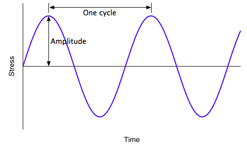
Of course, fatigue damage doesn’t always develop—if it did, everything we made would break. There’s a relationship between the amplitude of the repeated stress and the number of repetitions to failure. This is usually expressed as something known as an S-N curve, where S is the amplitude of the stress and N is the number of cycles.

For historical reasons, 1 fatigue strength is usually described in terms of fully reversed stresses, that is, stresses that swing between tension and compression. There are adjustments made to the S-N diagram when the stresses are always tensile.
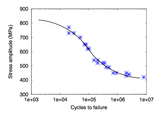
S-N curves are created by testing many samples of a material to failure. For each test, a stress amplitude is chosen and the piece is repeatedly loaded to that amplitude. When the piece fails, you plot the stress amplitude against the number of cycles it took to break it. Here’s an example for 517 steel, using data that I eyeballed from a plot in Norman Dowling’s excellent Mechanical Behavior of Materials.

The fatigue life—that is, the number of cycles to failure—can be very sensitive to stress amplitude, which is why S-N data are plotted on semi-log paper. After the points are plotted, the analyst fits a curve through them.
Using S-N curves is usually called the stress-based approach to fatigue analysis. It’s the simplest way to look at fatigue and the way that’s been used the longest. There are also strain-based and fracture mechanics approaches to fatigue analysis. The Wikipedia article on fatigue gives a decent overview of these approaches.
You can see from the x axis of S-N curve why fatigue, especially high-cycle fatigue toward the right end of the curve, wasn’t studied until the age of the steam engine. Before then, machines were driven by animal, wind, or water power and just didn’t go fast enough to develop millions of stress cycles.
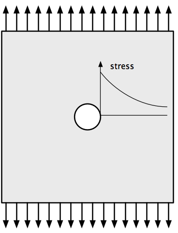
I mentioned earlier that fatigue is the accumulation of damage in a part. The damage takes the form of cracks, which generally start at holes, corners, or surface scratches that cause locally high stresses known as stress concentrations. The classic example of a stress concentration is a hole in a piece of sheet metal that’s being pulled.

At the edge of the hole, the stress is three times what it is in the rest of the sheet. This is a pronounced effect, but quite localized; within just one diameter of the hole’s edge, the stress has dropped off to about what it is elsewhere. Because of this locally high stress, this is a likely place for fatigue cracks to develop.
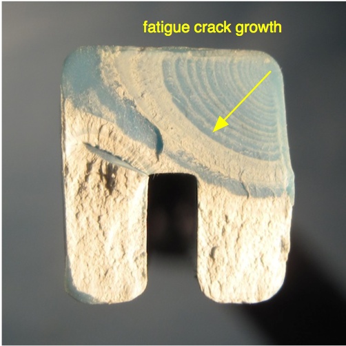
When a part has failed through fatigue, it often leaves an interesting pattern on the broken surface. Here’s the broken surface of a plastic arm that was once part of the flushing mechanism in my toilet tank.2

The crack started in the upper right corner and advanced down and to the left via fatigue. Every time the handle was pressed to flush the toilet, that was another cycle of stress on the arm. The fracture surface in the upper left quadrant is pretty flat, with arc-like marks sweeping across it. These are called beach marks because of their resemblance to the marks that waves leave on a sandy beach. They represent the state of the crack as it grew through the arm.3
After the crack had grown about halfway through the arm, the arm was no longer strong enough to withstand the force of a single flush, and the arm broke through the rest of the way. This last flush is represented on the fracture surface by the rough white areas in the lower half of the arm.
What the NTSB is doing now with the roof of Southwest Flight 812 is basically a more detailed version of what I did with this plastic arm: looking at the fracture surface to determine where the fatigue cracks started and how far they advanced before the final failure. They’ll use this information to develop new guidelines for inspection and repair of aircraft.
-
The earliest systematic study of fatigue came in the railroad industry to explain the failures of axles. Axles undergo what’s known as rotating bending fatigue, in which the surface stress on the axle goes from tension to compression with each rotation. After lots of data were developed for this problem, there was strong incentive to keep expressing fatigue properties in this form so comparisons could be made more easily. ↩
-
Not all engineering analysis deals with glamorous stuff like airplanes. It does seem odd, though, that I keep using my toilet to explain engineering principles. ↩
-
The individual marks do not typically represent one cycle of stress, so you can’t estimate the fatigue life of the arm by counting the beach marks like you’d count growth rings in a tree stump. There are, however, much more closely spaced marks, called striations, that do represent the crack’s growth with each cycle of stress. You need serious magnification to count striations, especially in the early stages of crack growth. ↩
