Let's twist again
September 29, 2011 at 1:30 PM by Dr. Drang
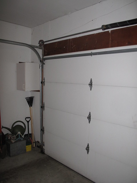
Sunday night, my wife and I heard a muffled bang that seemed to be coming from our garage. Expecting to find that a shovel had fallen off the wall rack and into my car, I went out to take a look. Nothing. Maybe the noise came from outside? I pushed the garage door button to go out, but the door wouldn’t lift more than a few inches before closing again. I looked above the door and saw why.
A torsion spring on the garage door just broke. Will need some feats of strength to get the cars out tomorrow.
It was too late to call a repairman, but I called first thing the next morning, and we had a working door again before noon. Because the springs were only 6-7 years old, I upgraded to a larger size that should have a much longer life. And I kept the broken spring to do a little failure analysis.
I had a pretty good guess at what the analysis would show. Fatigue is the obvious failure mode for a part that’s repeatedly loaded and unloaded. It did seem, though, that the spring had failed earlier than it should have.
Garage door springs probably see < 5000 cycles/year. Should easily last 20 years. These have been in about 10. Undersized?
That tweet was written before I found out how old the springs really were, but the rest of the math still seems right to me. I doubt that we open and close the door more than 10-15 times a day on the average, which works out to around 5,000 cycles per year, and it seemed to me that a fatigue life of over 100,000 cycles should be easy to attain.
I kept the broken spring and took it into the office to have a better look at it. I suppose I should mention that investigating failures makes up a good part of what I do for a living, so my company has a well-lit lab with microscopes and other equipment for inspecting and photographing broken parts.
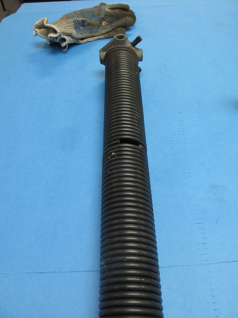
Here are the two halves of the broken spring laid out with a small gap at the fracture site.
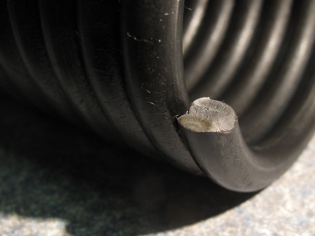
And here’s a closer view of the fracture.
Most of the fracture surface is the typical steel gray, but you can see a thumbnail-shaped area that’s a greenish brown. That area is very flat and the discoloration takes the form of a series of concentric arcs. Those arcs are known as beach marks because they look like the marks that waves leave on a sandy beach. They’re a characteristic of fatigue crack growth; the arcs represent the position of the advancing crack front as the crack grows slowly with cyclic loading. The discoloration is caused by oxidation of the newly exposed steel. Once the crack has reached a critical size, the wire can no longer support the loads imposed on it, and the final fracture—the gray area—occurs rapidly in a single event.
The origin of the fatigue crack can be found by working inward through the concentric arcs. Here, the origin is at the outer edge of the wire. Sometimes fatigue cracks grow out of surface defects, like scratches or nicks, but I saw no surface defects in my spring.
To figure out whether the location of the origin makes sense, we’ll have to consider the state of stress in the spring. There’ll be a little bit of math coming up, but not too much.
I have a few books that cover the analysis and design of springs. My favorite is Merhyle Spotts’ Design of Machine Elements. I have a copy of the second edition, published in 1953, and it’s a marvel of clarity—he managed to be brief without omitting essential details, a rare thing. I met Merhyle a few times in the mid-80s when he was about 90 years old and still sharp as a tack. At that time, Design of Machine Elements was in its 5th or 6th edition and was one of the common texts used in mechanical design courses. Merhyle died in the 90s, a few months shy of his 99th birthday, but the book lived on. It’s now in its 8th edition and has picked up a couple of coauthors. The Amazon reviews of the current edition are brutal; I don’t know if the reviewers are idiots or the coauthors have ruined it, but if I were in the market for a mechanical design book, I’d search AbeBooks for an older, single-author edition.
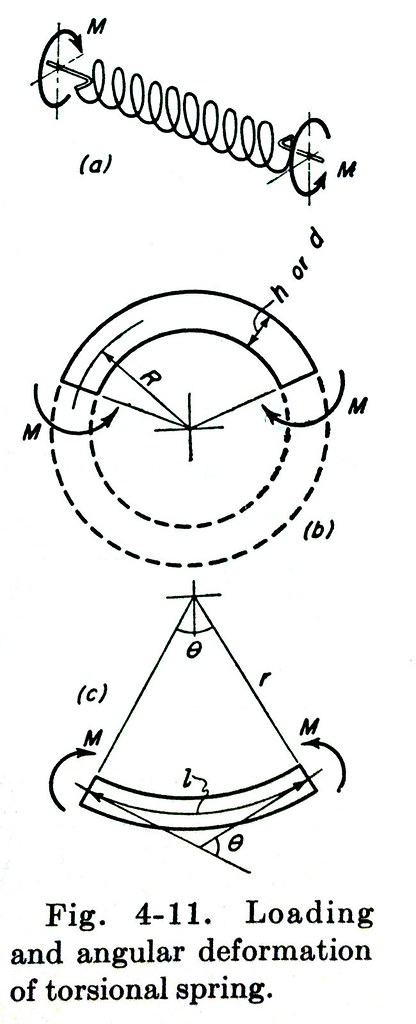
Here’s the figure from Design of Machine Elements that describes the behavior of a coiled spring under a torsional load:
The torque applied to the spring as a whole, , becomes the bending moment applied to the curved wire. Because there are no intermediate loads, the bending moment is constant throughout the length of the wire. The change in curvature of the wire can be calculated through the standard formula
where is the modulus of elasticity (30,000,000 psi for steel) and is the wire’s moment of inertia. For a round wire of diameter , like in my torsion spring,
The rotation of one end of the spring relative to the other, , is the product of this curvature change and the total length of the wire:
where is the radius of the spring (to the centerline of the wire) and is the number of coils in the spring. In the illustration from Merhyle’s book, the spring wire goes around 10½ times, so .
The spring follows Hooke’s Law, and its spring constant is the constant of proportionality between and :
In an engineering text, the usual units for a torsional spring constant would be something like inch-pounds per radian, but that’s not how people in the garage door industry describe their springs. The repairman who replaced my springs had a book for choosing the appropriate spring for a given door. The available springs are categorized according to
- spring diameter
- wire diameter
- IPPT
IPPT, I learned, stands for “inch-pounds per turn,” a more convenient way of describing the spring constant to someone working in the field. In this case, “turn” means one full rotation of the end of the spring: a rotation of radians. Using our nomenclature,
My broken spring had an inside diameter (ID) of 1.75″, a wire diameter of 0.234″ and 136 “active” coils. What’s an active coil?. It’s a coil that tightens when the spring is wound. There are fittings at either end of the spring (you can see one of them in the photo above) that freeze a few end coils and prevent them from tightening. These inactive coils aren’t counted when determining .
Using these values, we can say
This is all very nice, but what does it have to do with the state of stress in the wire? We’re getting there. Let’s talk about how the spring works to help raise the door.
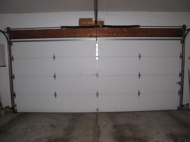
Here’s my garage door. It has two torsion springs on a long horizontal shaft mounted on the header above the door. The ends of the springs at the center of the door are attached to a stationary mounting plate, and the outer ends are attached to the shaft and turn with it. At either end of the shaft is a pulley with a cable that runs down to the bottom corner of the door. The springs are at their most tightly wound when the door is closed, so they’re trying to turn the shaft and pull up on the door. As the door opens, the springs help the motor lift the door. As the shaft turns, the springs unwind and the lift they provide lessens, but that’s OK because as the sections of the door rise and turn the corner of the track, less force is needed to lift the remaining vertical portion of the door.
When the door is open, the spring is still wound a bit, about 1 turn. When the door is closed, it’s wound about 7½ turns. Therefore, the torque in the spring varies from
to
and, as we learned from Merhyle’s drawing, that’s the bending moment applied to the spring wire.
If you’ve had a course in strength of materials, you know that the maximum stress in a straight beam can be determined by the equation
where is the distance from the centroid to the outer edge of the beam’s cross-section. For a circular cross-section like we have here,
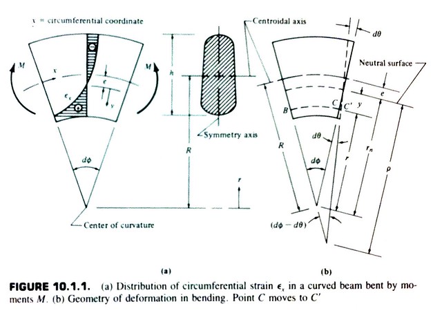
When the beam is curved, like our spring wire, things aren’t quite so simple. The neutral surface (where the stresses and strains are zero) is shifted away from the centroid, and the stress is no longer proportional to the distance from the neutral surface. Here’s an illustration from another favorite book of mine, Cook and Young’s Advanced Mechanics of Materials, that shows the behavior quite well on a small wedge section of a beam.
Exactly how the stresses vary from the straight-beam solution depends on the shape of the cross-section and the initial curvature of the beam. Fortunately for us, Spotts has provided formulas for the common shapes of spring wire. For a round wire, the stress on the inner edge of the wire is
and the stress on the outer edge of the wire is
where
I’m playing a bit fast and loose with the signs of the stresses because I’m assuming that we can figure out from the direction of the bending moment which edge of the wire is in tension and which is in compression. When the spring is wound tighter, as it is in garage door springs, the inner edge is in compression and the outer edge is in tension. That’s why our fatigue crack started at the outer edge. Since it’s only tensile stresses that contribute to fatigue cracking, we’ll focus our attention on the stresses at the outer edge.
For my spring, , and therefore the tensile stress on the outer edge of the spring varies from
when the door is open to
when the door is closed. This seems like both a high maximum stress and a high stress range, but whether it is or not depends on the properties of the steel the spring is made of.
Garage door springs are typically made from an oil-tempered steel that conforms to ASTM A229, a standard that governs the chemistry and mechanical properties of the steel. Unfortunately, the mandated tensile strength of A229 steel can be as low as 191,000 psi or as high as 324,000 psi, and I have no idea where my spring lies within that spread. If this were a real failure analysis—and by “real” I mean one that I’m getting paid for—I’d cut a sample from the spring and send it to a metallurgical lab to have hardness tests run on it. Hardness doesn’t correlate perfectly with strength, but there are decent conversion tables.
But even without a precise value for the strength, it’s clear that the stress range is a big fraction of the tensile strength, and that’s why the springs have a finite life.
In fact, the repairman’s book included an estimated life for each spring. My old springs were rated for 50,000 cycles, which would be about 10 years if my earlier usage estimates are right. Fatigue life is notoriously hard to predict outside of laboratory conditions (despite what you may have heard from Jimmy Stewart) and is usually based on some sort of statistical estimate. Depending on the statistical criterion used to create the rating, my six- to seven-year life may have been unlucky, but not tremendously so. The plain fact of the matter is that these springs are expected to fail—mine just failed a little earlier than normal.
My new springs have a larger coil diameter (), a larger wire diameter (), and more coils (). This puts the spring rate at
which is pretty close to that of the old spring. The spring rate should match closely to keep the overall balance of the door the same. The stress range is from 20,500 psi when the door is open to 153,700 psi when the door is closed. This is about a 15% reduction in both the maximum stress and the stress range, which may not seem like much, but fatigue life is pretty sensitive to stress, and when the life is on the order of to cycles a 15% reduction in strength can lead to a huge increase in life. The repairman’s book says the new springs should last 100,000 cycles. Unless I have another bad-luck spring, this set should last 20 years.
I hope so. I really don’t want to have to write this post again.


