Accelerometers
May 27, 2012 at 9:28 PM by Dr. Drang
Gabe linked to this recent video by Bill Hammack in which he talks about the workings of the accelerometers in our smartphones. You may have also seen it on Boing Boing.
This is one of his best videos. It’s an especially good introduction to how silicon etching is used to create tiny machines.
But…
But if you didn’t know better, you’d get the impression that the purpose of the accelerometers is to determine a device’s static orientation. And although they can do that, the true purpose of accelerometers is to measure—no surprise here—acceleration, a distinctly dynamic quantity.
I understand why Prof. Hammack stuck with statics. It’s easier to explain in a short video, where you really can’t get into the differential equations of motion. Lucky for you, I don’t feel any such constraint here.
Let’s start by simplifying the problem. Your phone (and your Wii controller, I believe) have three accelerometers oriented at right angles to one another. We’re going to study the behavior of just one accelerometer. Once you understand the behavior of one, extending it to three is easy.
Accelerometers can be made in many different ways, but they all have three essential parts:
- A mass that can move relative to the accelerometer’s housing.
- A spring that connects the mass to the housing.
- A damper that dissipates energy and keeps the spring-mass system from vibrating forever.
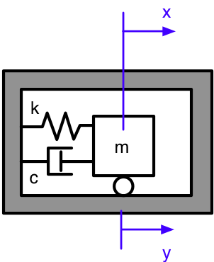
Conceptually, at least, they all look like this:
where
- is the mass of the moving block.
- is the stiffness of the spring.
- is the damping constant.
- is the position of the moving block relative to an inertial (stationary) frame of reference.
- is the position of the housing relative to the same inertial frame.
While this doesn’t look like the accelerometer Prof. Hammack is demonstrating, it is an abstraction of all the important features. If you go back and look at the video, at about 1:40 you’ll see this drawing of the accelerometer:
The “seismic mass” is the moving block; the four arms at the ends of the block act as the springs; and the position of the block relative to the housing, equivalent to the difference , is monitored through the capacitance of the green and blue “fingers.” Not shown explicitly is friction, which acts as the damping on the system.
Let’s assume the housing is being shaken back and forth in a sinusoidal motion:
where is the amplitude of the motion, and is its frequency1.
The motion of the moving block is governed by this differential equation:
Borrowing some notation from Isaac Newton, we’re using dots to represent differentiation with respect to time. is the acceleration of the block relative to the inertial frame. The damping force is proportional to the rate of extension of the dashpot, , and acts opposite to its direction. The restoring force is proportional to the extension of the spring, , and acts opposite to its direction.
Solving the equation is easier if we rewrite it in terms of the motion of the mass relative to the housing,
which gives us, after differentiating the expression for and a little algebraic rearrangement:
The steady-state2 solution is a sinusoid with the same frequency as the housing. It has the compact form
where is the amplitude and is the phase angle. The phase angle, which represents how much the motion of the mass lags behind the motion of the housing, isn’t of great interest to us here, so we’ll concentrate on the expression for the amplitude,
where
is the natural frequency of the system, and
is the nondimensional damping coefficient or damping ratio.
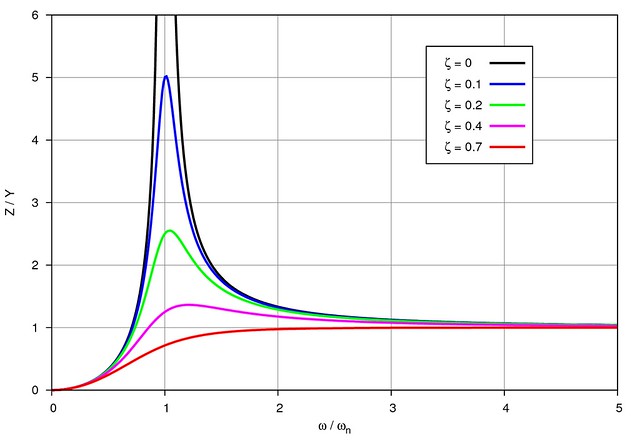
Here’s a plot of the amplitude equation (after normalizing by dividing both sides by ) for a few values of the damping ratio.
You were probably expecting to see those peaks near ; that’s the condition known as resonance. What you may not have been expecting is to see tend toward as increases. What this means is that if the shaking frequency, , is much higher than the natural frequency, , the amplitude of the response will be, for all practical purposes, equal to the amplitude of the shaking.
This is the behavior of a seismometer, which is built to measure ground displacement during an earthquake. Seismometers need to have a very low natural frequency, so they’re made with relatively large masses and flexible springs. During an earthquake, the seismometer’s housing shakes with the ground, while the mass inside remains practically motionless due to its large inertia and flexible connection to the housing. The relative motion between the mass and the housing, therefore, is a good measure of the ground displacement.
That’s all very well and good, you may be saying, but we were supposed to be talking about accelerometers, not seismometers. True enough. Let’s rearrange the equation for slightly:
What makes this rearrangement interesting is that the numerator of the right hand side, , is the amplitude of the acceleration of the housing. Recall that
Differentiating this twice with respect to gives
so is the amplitude of . (The minus sign just means that the acceleration of the housing is 180° out of phase with its displacement.)
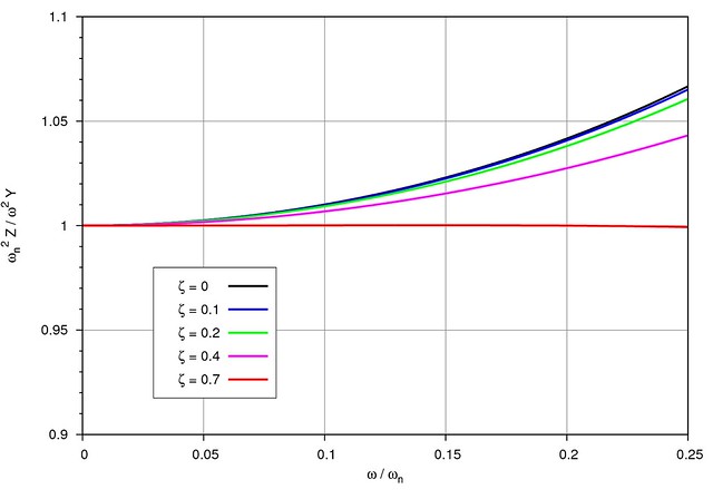
Let’s normalize the equation by dividing both sides by and plot the result, this time for small values of :
We see that for small values of . This is the key to the design of an accelerometer. If we make our spring-mass-damper system with a relatively small mass and stiff spring, we’ll get a high , and if the shaking frequency of the housing is low compared to that, the displacement of the mass, will be proportional to the acceleration of the housing. We can measure the displacement of the mass within the housing (using the capacitance change Prof. Hammack talked about), multiply it by the known natural frequency of the accelerometer, and we end up with the acceleration of the housing.
Stick three of them together in mutually perpendicular directions and you can, by combining the results vectorially, determine the acceleration in any direction.
There’s one last detail that needs to be accounted for: gravity. Gravity will cause the mass of an accelerometer oriented vertically to move downward the same amount as it would if it were in a weightless environment and accelerating up at one gee. An accelerometer permanently mounted in a vertical direction can be set up so its output adjusts for this and reports true acceleration. A phone’s accelerometers, however, can be in any orientation, so there’s no way to correct for that; they will report an upward acceleration of one gee even when they’re sitting stationary.
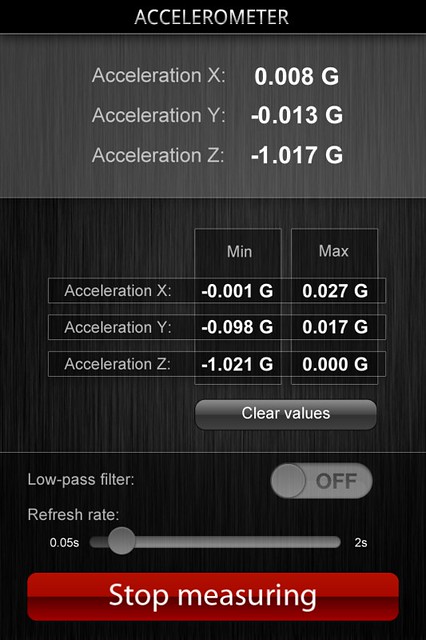
You can see this in a screenshot of the generically named Accelerometer app, a $1 iPhone app that displays the realtime outputs of all three accelerometers as well as the maximum and minimum values during a recording session. I had my phone sitting flat on a table when I took the screenshot, and the acceleration along the “z-axis”—which is apparently through the thickness of the phone—is reported to be about -1 gee.
This one-gee offset, although it’s a false reading for acceleration, is valuable. It’s how the orientation of the phone is determined, which brings us back around to Prof. Hammack’s video. Now we see why something that’s supposed to be measuring acceleration pulls double-duty for orientation, too.
Update 5/29/12
I discuss the Gnuplot commands used to generate the plots in this post.
-
This is a circular frequency and is measured in radians per second. You may be more familiar with cyclic frequency measured in Hertz, or cycles per second. These two ways of describing frequency are proportional to one another, and the proportionality constant is because there are radians in one cycle. Cyclic frequency is easier to measure, but circular frequency is easier to use in equations. ↩
-
Immediately after the shaking starts, there is some motion not described by this equation, but that motion quickly damps out, leaving just the simple steady-state motion. ↩


