Damped free vibrations
April 12, 2014 at 1:03 AM by Dr. Drang
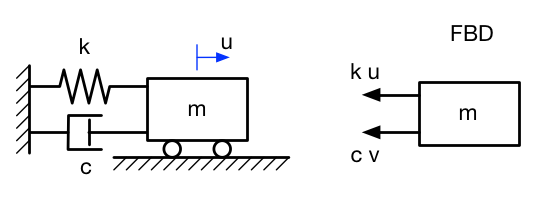
The second simplest vibrating system is composed of a spring, a mass, and a damper.
We’ve seen the spring and the mass before, so let’s talk about the damper.
The image typically used to represent a damper is meant to look like the cross-section of a hydraulic cylinder1 with a leaky piston, a device called a dashpot. You’re supposed to imagine the fluid in the cylinder squirting around the edges of the piston; it doesn’t stop the movement of the piston, but it does slow it down. Strictly speaking, this kind of damping is called viscous damping, but the word viscous is often dropped.
The force exerted by a dashpot is proportional to the speed at which the piston moves and is directed in opposition to the movement, so when we construct the free-body diagram of the mass, assuming both displacement and velocity in the positive direction, we get the figure on the right and this equation of motion:
where is the constant of proportionality between the damper’s force and the speed at which it’s extended or retracted. The other symbols have the same meaning as in the undamped case.
Rearranging into the usual form,
we get a second order, linear differential equation with constant coefficients. This is—lucky us—one of the differential equation forms that can actually be solved without resorting to numerical methods. It’s common to divide through by and introduce some new variables.
where
is the undamped natural frequency of the system, which we’ve seen before, and
is the damping coefficient.2 It is a dimensionless quantity, because has the units
and so does .
The quantity is called the critical damping constant, . The damping coefficient is therefore often defined this way:
What makes critical damping critical? From a mathematical point of view, critical damping represents a change in the the nature of the solution of the differential equation. John Cook did a good job explaining that in his post on damped vibrations, so I’ll just refer you there. From a physical point of view, critical damping represents the boundary between oscillatory behavior and non-oscillatory behavior. The system oscillates about the equilibrium position only if the damping is less than critical: or . This is called the underdamped case and is the one we’ll be exploring.3
The oscillatory solution can be written as
where and are the displacement and velocity at , and
is called the damped frequency for reasons that will become clear soon. The solution can also be written more compactly as
You may recall from our look at undamped free vibrations that the phase angle, , is somewhat arbitrary—it’s value is determined by when we decide to say . Therefore, we can choose a starting time that makes and simplify our equations and graphs even more.
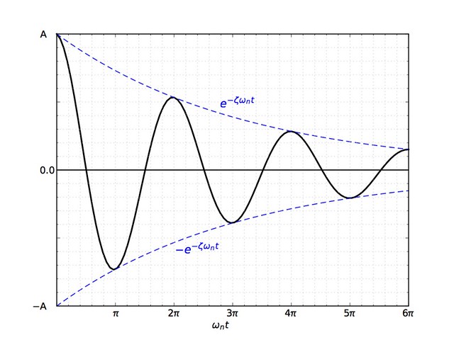
The solution for and looks like this, a decaying sinusoid:
The exponential term acts as an envelope that lowers the amplitude of the oscillation as time marches on. The points of tangency, where the black solution curve touches the dashed blue envelope, are where . The upper points of tangency are spaced
apart, as are the lower points of tangency. is the damped period of the system. For small values of , and .
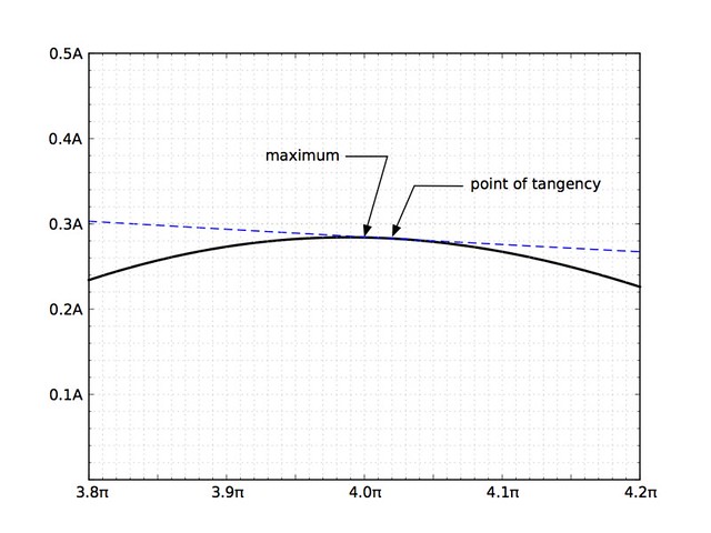
If you zoom in, you can see that the maxima and minima of the curve don’t quite match up with the points of tangency.
It can be shown, however, that the time between successive maxima (or successive minima) is the same as the time between successive points of tangency. This is very convenient if you want to measure the damped period of a system experimentally. When you’re monitoring the vibration of a system, the maxima and minima are relatively easy to determine—the points of tangency are impossible.
Similarly, the amplitude ratio between successive maxima is equal to the amplitude ratio between successive upper tangency points. If we call each maximum , where is an integer, then
If we take the natural logarithm of both sides, we get
which is called the log decrement of the damped oscillation. We can determine the damping coefficient experimentally by measuring the displacement at successive maxima, taking the natural log of their ratio (that’s ), and calculating by a rearrangement of the above equation:
I’ve always thought of the damping coefficient and log decrement as conceptually similar to the coefficient of restitution of a bouncing ball. In both cases, we’re tracking the decay of successive “high points” in the motion of an object. They also represent a loss of mechanical energy from the system, a point we’ll discuss in a later post.
When we looked at undamped systems, we found that their behavior is governed by their natural frequency, , and that we can determine experimentally without knowing either or . Now we see that the behavior of a damped system is governed by and 4 and that we can determine them experimentally without knowing , , or .
Mechanical systems have springy parts and they have mass, but very few have actual dashpots. What good is all this math if it doesn’t represent actual equipment? We’ll talk about the kinds of real-world things we model as dashpots next time.
-
This is sort of like the kind of hydraulic cylinders you see on construction equipment, but it isn’t being driven by pumps. All the fluid stays in the cylinder—it just moves from one side of the piston to the other as the piston moves back and forth. ↩
-
In case you’re rusty with your Greek alphabet, that’s the letter zeta. ↩
-
Although it’s called underdamped, you shouldn’t think of it as having some deficiency. There can be plenty of damping in an underdamped system. The “under” just means the system oscillates. ↩
-
And the natural frequency, but once we have the damped frequency and the damping coefficient, the natural frequency is easy to calculate. ↩


