Super
August 19, 2015 at 11:59 PM by Dr. Drang
I know you don’t really care about this, but last night’s post put me in the mood to do more old-fashioned structural analysis, so I’m going to show how to solve one more example problem by the Myosotis method. In this one we’ll use superposition and compatibility to solve a statically indeterminate problem.
Here’s the problem: a propped cantilever beam with a uniformly distributed load. The prop is the simple support out at the right end of the beam.
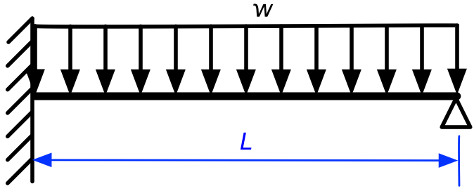
This problem is statically indeterminate because it cannot be solved by the equations of statics alone. No matter how many ways we set up free-body diagrams, we’ll never be able to determine the reactions at the ends of the beam. But that doesn’t mean the problem can’t be solved; we just have to account for the deflections of the beam and develop additional equations to ensure that those deflections are compatible with the support constraints.
In addition to compatibility, we’re also going to take advantage of the principle of superposition. When a structure is made of linearly elastic material and its deflections are relatively small, the principle of superposition says that the solution for a structure subjected to multiple loads is equal to the sum of the solutions for that same structure subjected to each individual load.
For our problem, we’re going to consider the upward force from the prop at the right end to be the second force acting on the structure. That way, we can break down our propped cantilever problem into the sum of two regular cantilever problems.
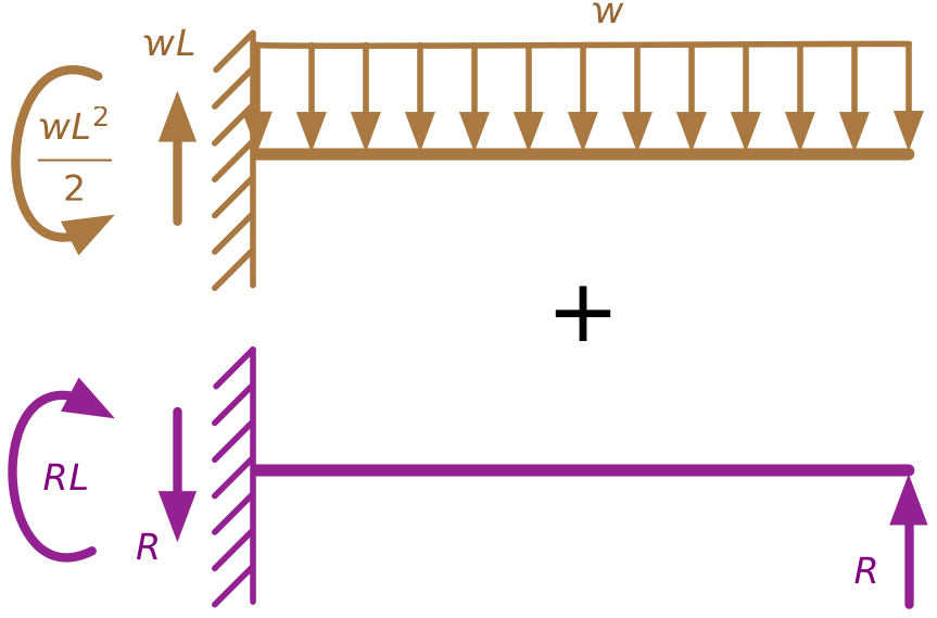
I’ve used color coding to identify the two separate load conditions, and we’ll use that same coding to keep track of the two solutions.
Each of these component problems is statically determinate and is one of the Myosotis problems:

Initially, we don’t know the value of the upward force, , at the right end of the second problem, but we can use compatibility to figure it out. In the original problem, the deflection at the right end of the beam is zero. If we set to a value that makes the upward deflection of the right end of the purple beam equal to the downward deflection of the right end of the brown, we’ll satisfy the compatibility constraint of the original problem. In equation form, that means
Solving for , we get
With the solution for in hand, we can easily determine that the upward reaction force at the left end is
and the counterclockwise reaction moment at the left end is
but we can go further than that.
To calculate the stresses in the beam, we must first determine the internal shear force and bending moment along the length of the beam. Structural engineers typically do this by drawing shear and moment diagrams for the beam. The great thing about superposition is that the shear and moment diagrams, like the support reactions, are simply additive. To get the shear and moment diagrams for the original problem, we need only add the shear and moment diagrams for the two simpler component problems.
Here are the shear diagrams for the two component problems, drawn on the same graph:
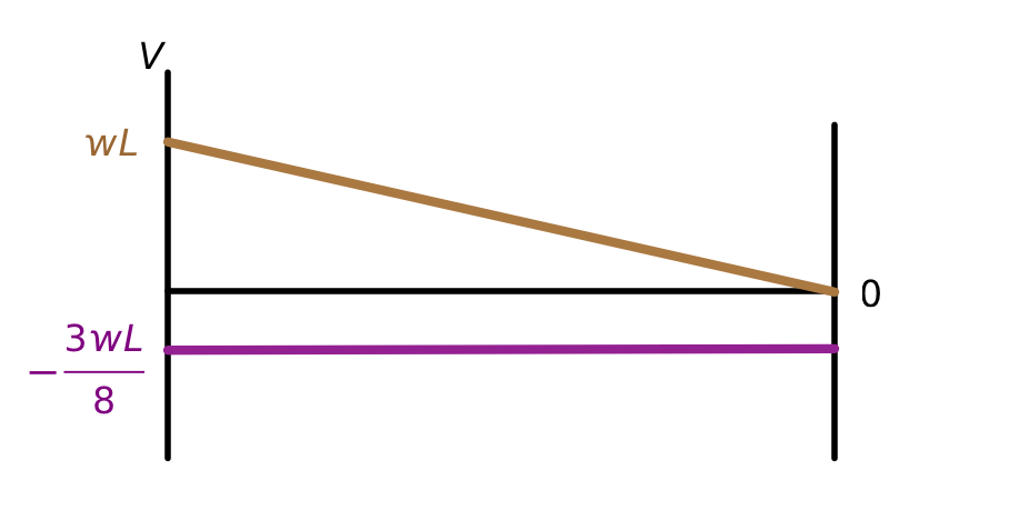
Shear is usually denoted by the symbol because it represents a vertical internal load. Adding these two component diagrams together yields this shear diagram for the original propped cantilever problem:
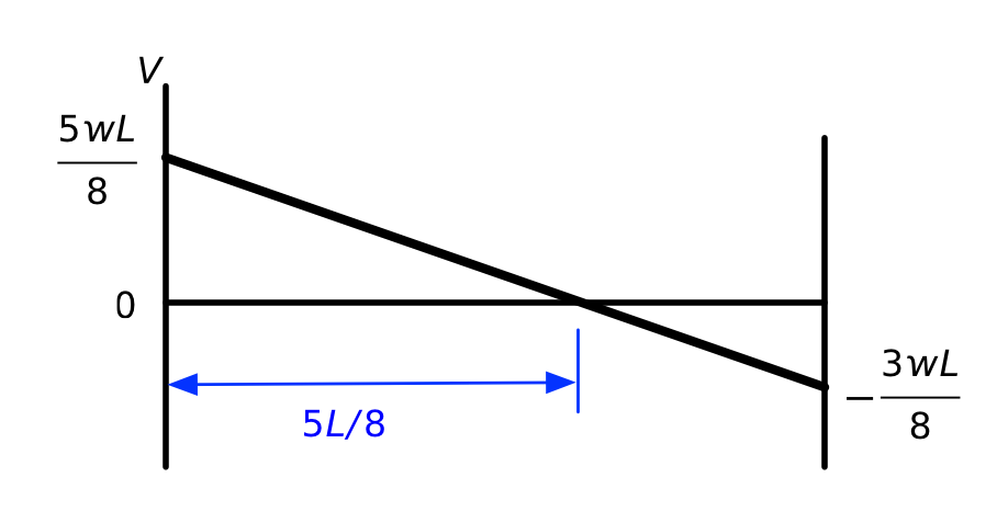
We see that the shear is positive at the left end of the beam and negative at the right end. It goes through zero at a distance from the left end. This is important to know because the bending moment will be at a local maximum or minimum where the shear is zero.
We can do the same thing for bending moment. Here are the two component moment diagrams, drawn on the same graph:
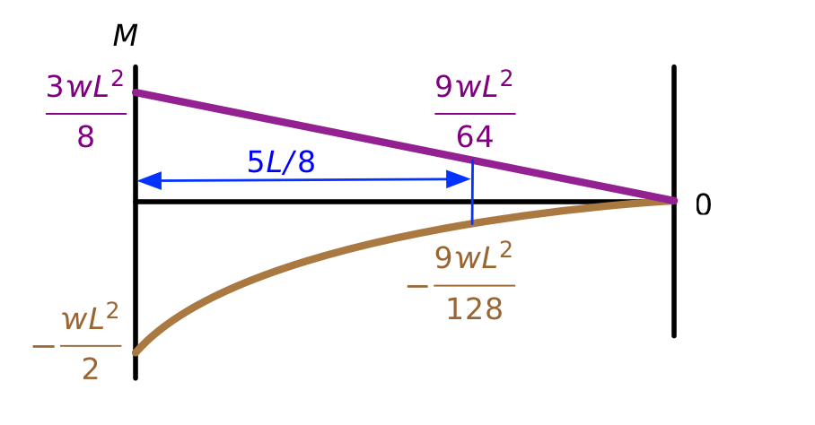
The brown one is a parabola and the purple one is a straight line. Adding the two together results in this parabolic diagram for the bending moment of the original propped cantilever.
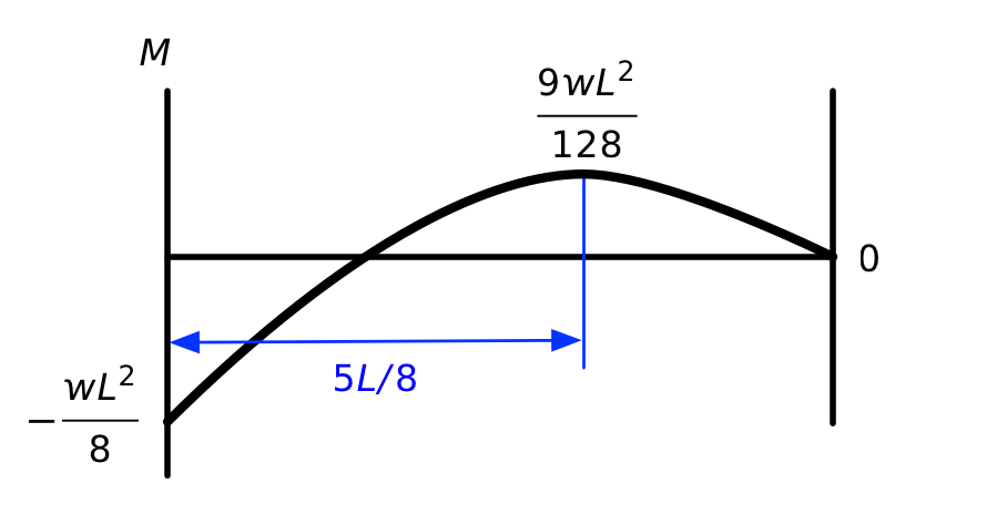
We see here the local maximum at the point. I’m using the usual sign convention for bending moments: positive moment puts the bottom of the beam in tension, negative moment puts the top of the beam in tension.
In case you’re wondering if this really is the correct solution, we can check it against tabulated values. Here’s one from the AISC Manual of Steel Construction:

They have the fixed and simple ends flipped around, but it’s still easy to see that all of our answers are correct.
OK, now that I’ve gotten that out of my system, I’ll go back to the usual crap I post here.
