Experimental mechanics
July 11, 2017 at 11:42 PM by Dr. Drang
A few days ago I got a call from a friend with an interesting problem. He’s investigating the failure of a long hollow steel rod, a rod that was said to have undergone helical buckling, and he wanted some help understanding the stresses and strains the rod had been subjected to when it buckled. I’ve done a lot of buckling analysis but never of helical buckling, so I told him I’d have to do a little studying and get back to him.
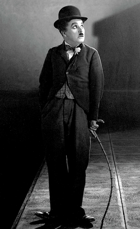
Helical buckling is a phenomenon that’s well known in the oil drilling and related industries but almost unheard of elsewhere. It occurs when a long rod that’s loosely encased in a larger diameter tube is compressed beyond its stability limit. If it weren’t for the tube that surrounds it, the rod would simply bow out to the side like Charlie Chaplin’s cane.

But the surrounding tube constrains the buckling rod, and if you keep compressing it, it will eventually wind itself into a helix in contact with the inner wall of the outer tube. The equations of a helix are fairly simple, so it’s easy to describe the midline of the buckled rod, but I was interested in whether the cross-section of the rod would rotate about its midline as it buckled, something the equations of the midline don’t tell you. It seemed from what I’d read that the cross-section shouldn’t rotate, but I wanted to see it for myself—not in a drawing, but in the flesh.
Not having hundreds of feet of steel tubing at my disposal, I started looking around the office for things I could put together. Here’s what I came up with:

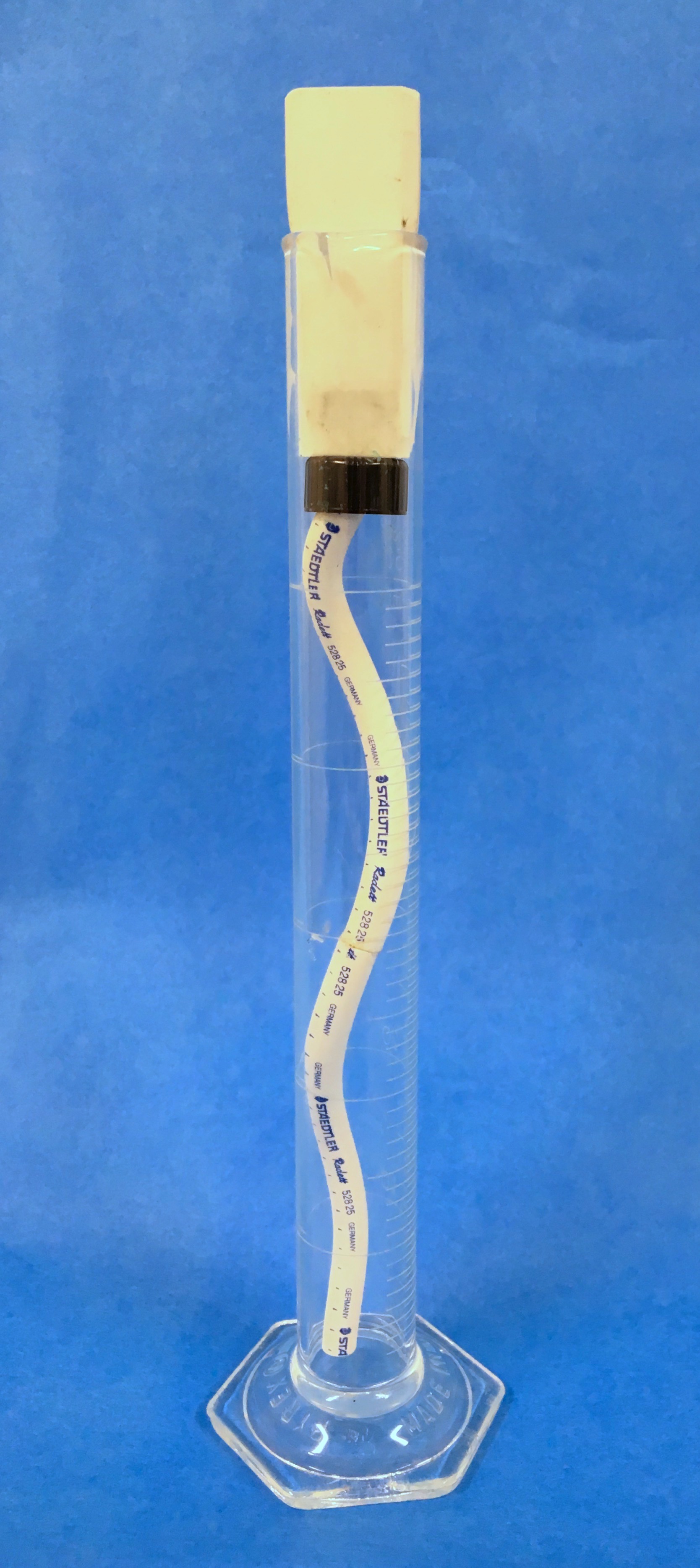
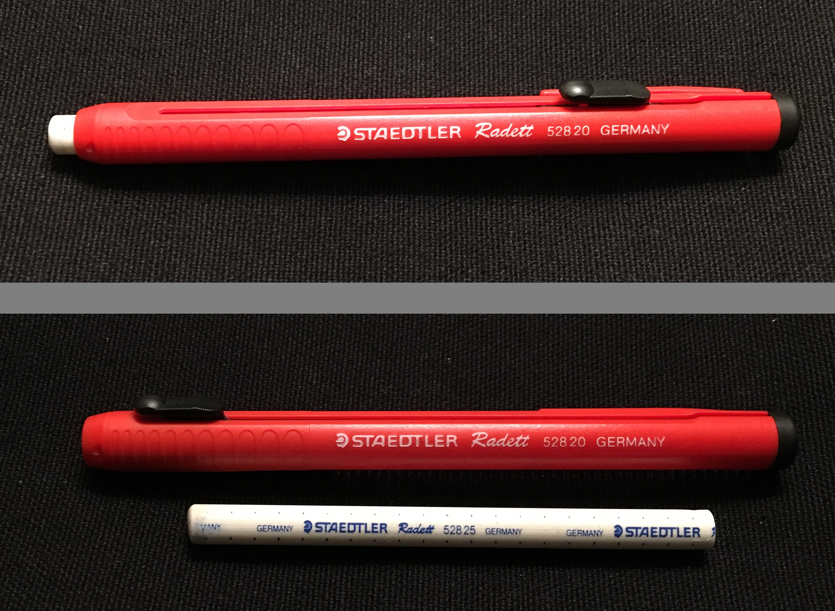
The rod is two plastic stick eraser refills glued together end-to-end. The enclosing tube is a graduated cylinder. We had lots of PVC and metal tubes around the office, but the graduated cylinder was the obvious choice1 because it allowed me to see the buckled rod inside it. The black thing on top of the rod is the cap from a vial that fits fairly nicely in the cylinder and holds the top of the rod. Finally, the white plug at the top of the cylinder is a plastic block eraser that I trimmed down to fit snugly in the cylinder. When I pushed the block eraser down into the cylinder, it buckled the rod into a helix and held it there.
Can you see that the rod is helical? If it looks more like a plane sinusoid to you, this video may help.
Except at the very bottom, the rod is up against the inside of the glass cylinder.
Looking back at the photo, you can see that the writing along the rod is always facing towards us. Therefore, the cross-section doesn’t rotate during the buckling. This is what I’d read, but now I could visualize it, and I felt more comfortable using the equations for stress and strain.
Although I spent a lot of time in school learning analytical techniques, most of my professors (the ones whose lessons stuck with me) emphasized the importance of physical understanding, how to “think like the structure” before doing any calculations. And when the structure is too smart for me, I try to make little models like this so I can learn how it thinks.
-
I was going to say “the clear choice,” but I didn’t want to make such a transparent pun. ↩


