Beams and forget-me-nots
August 18, 2015 at 11:20 PM by Dr. Drang
Do you read John D. Cook’s Endeavor blog? If you have any interest in recreational mathematics, you’ll enjoy it. Today he wrote a short post on something that’s far more than recreational to me: the equations of beam bending, a topic I’ve been studying for over 35 years.
The particular equations Cook presents are the Myosotis equations, popularized by J.P. Den Hartog in his wonderful little Strength of Materials book. Here’s how they’re presented in the book:

Myosotis is the genus of the forget-me-not flower, and Den Hartog expected his students to memorize these six equations.
The expressions should be memorized from the start, which is not difficult if we only remember the sequence 122368. If the exponent of the length l is forgotten, it can be reestablised in each case by dimensional reasoning.
The formulas are for the rotation angle and deflection at the tip of a cantilever beam1 under the three loading conditions given in the drawing: a concentrated bending moment at the free end, a concentrated force at the free end, and a uniformly distributed force along the length of the beam.
In the equations, , , and are the magnitudes of the applied loading, is the length of the beam, is the modulus of elasticity of the beam material, and is the moment of inertia (or second moment of area) of the beam cross-section.
Missing from Cook’s post is an explanation of why these equations are worth memorizing. It’s not because they’re used directly in the analysis of typical engineering structures. Although engineers do encounter cantilever beams loaded like this, they certainly aren’t the most common beam configurations they’ll run into in professional practice. What makes these equations valuable is how they can be combined to solve many practical beam bending problems.
Here’s an elementary example, a simply supported beam2 with a concentrated load at its center. We need to determine the deflection under the load.

This is not a condition covered by the Myosotis equations, but we can manipulate it into one that is. Notice first that the beam, its supports, and its loading are all symmetric about the center. That means the deflection curve of the beam, shown (greatly exaggerated) in purple, will be symmetric, too, and the slope at the center will be zero.
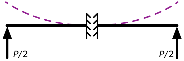
Therefore, we can think of our simply supported beam as being just like two back-to-back cantilever beams with upward loads at their tips.

Each of these conceptual cantilever beams is of length and the upward loads at their tips are equal to the reaction forces at the supports of the original problem, . So the deflection, , at the center of the original beam is equal to the tip deflection of either conceptual cantilever. Using the Myosotis deflection equation in the second row of Den Hartog’s figure and plugging in for the tip force and for the cantilever length, we get
which you can confirm as the correct result by referring to Case 7 of this table of beam solutions.
The point of the Myosotis method is to be able to solve a tremendous number of practical problems relatively easily while memorizing only six formulas. That’s why Den Hartog says of them
After the alphabet and the tables of multiplication, nothing has proved quite so useful in my professional life as these six little expressions.
which is the quote Cook uses to lead off his post. In case you haven’t guessed, Den Hartog’s career came long before computers were available to generate numerical solutions to beam problems at a moment’s notice. The Myosotis formulas aren’t nearly as useful to me as they were to Den Hartog, but I still solve some problems with them. Memory, a couple of sketches on sheet of paper, and little imagination can still be faster than typing numbers into a computer.
-
Cantiever beams have one end that’s “fixed”—unable to deflect or rotate—and another end that free to both deflect and rotate. A fixed end is typically shown in drawings as a straight line with hashing behind it, as shown at the left end of each beam in the Den Hartog drawing. ↩
-
“Simple” supports prevent deflection but allow rotation. If you set a wooden plank on rocks to span the distance between them, the rocks would constitute simple supports. In drawings, simple supports are typically represented by little triangles, as I’ve done here. ↩
