Lagrange points redux
August 17, 2016 at 6:23 PM by Dr. Drang
About a year ago, inspired by this GIF from the DSCOVR satellite, I wrote a post about the first Lagrange point of the Sun-Earth system, which is where DSCOVR is located. I wanted someday to return to the topic and get the locations of all the Lagrange points. This is the day.

Background
Lagrange
Lagrange points are points in the orbital plane of a planet1 that orbit the sun with the same period as the planet. You might think you could put a satellite at any point along a planet’s orbital path and Kepler’s laws would ensure that it has the same period as the planet. But Kepler’s laws apply only to a two-body system. This is a three-body problem, in which the satellite’s motion is influenced by the gravitational pulls of both the sun and the planet. While there is no solution to the general three-body problem, the Lagrange points—so named because they were worked out by the 18th century natural philosopher Joseph-Louis Lagrange—represent special cases where the solution is possible.
In last year’s post, I showed how to find the first Lagrange point, L1, by balancing the two gravitational forces acting on it to create a centripetal acceleration that keeps a satellite at L1 in place. This approach works, but it’s a very non-Lagrangian way of solving the problem.
Lagrange was all about energy. He took Newtonian mechanics and recast it to eliminate the need to balance forces and inertias. In Lagrangian mechanics, you get solutions by taking derivatives of the kinetic and potential energy functions. It’s an elegant technique, well suited to the explosion of analysis on the Continent back at that time.
Two-body results
Let’s start by assuming we’ve already solved the two-body problem of a sun and its planet in a circular orbit. We’ll take their masses to be and , respectively, and the distance between their centers to be . We’ll then introduce a nondimensional quantity, , to represent the planet’s fraction of the total mass, . Thus,
The center of mass of the two-body system—which astronomers call the barycenter because it sounds more scientific—is on a line between the two bodies a distance from the sun and from the planet. Both the sun and the planet revolve about the barycenter with an angular speed , where
The period is related to the angular speed through the relation
which leads to the well-known expression for Kepler’s Third Law, which states that the square of the period is proportional to the cube of the distance:
With these preliminaries out of the way, let’s move on to finding the Lagrange points. I want to start by pointing you to an excellent online resource, Richard Fitzpatrick’s Newtonian Dyanamics, which is available in both PDF and HTML format. Fitzpatrick, who teaches at the University of Texas at Austin (hook ’em), does a very nice job of explaining both the two-body problem and the restricted three-body problem. There’s one trick in particular that I stole directly from him to simplify a potential energy expression.
Energy
Reference frame
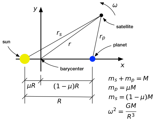
Here is our system of sun (yellow), planet (blue), and satellite (black) laid out on an coordinate system. We put the origin at the barycenter and the on the line between the sun and the planet. Furthermore, we’re going to have our coordinate system rotate at a constant angular speed of , precisely matching the movement of the sun and the planet about the barycenter. This will be our reference frame for the analysis. The advantage of using a rotating reference frame is that the sun and planet are, by definition, motionless in this frame, and our search for Lagrange points is reduced to finding points where the satellite will be motionless, too.
You may object to using a rotating reference frame.
A rotating reference frame isn’t inertial. That’s true.
You can’t do an analysis in a non-inertial reference frame. That’s not true.
Non-inertial reference frames are perfectly fine as long as you account for the acceleration terms correctly. This is the deeper truth behind d’Alembert’s Principle. Most of us learn d’Alembert’s Principle as simply moving the acceleration term in Newton’s Second Law over to the other side of the equation and treating it as an additional force.
But d’Alembert works in an energy context, too.
Potential energy
In our rotating frame of reference, the potential energy of the satellite has three terms.
The first two terms are the gravitational potential energy due to the sun and the planet, respectively, and the third term is the centrifugal potential energy due to the rotating frame. The third term wouldn’t appear in a potential energy expression written for an intertial frame.2
In the expression for ,
- is the mass of the satellite,
- is its distance from the center of rotation (the barycenter),
- is its distance from the sun, and
- is its distance from the planet.
See the figure above for details.
Non-dimensional form
The first thing to do is substitute our previous expressions for , , and into the expression for .
We’re starting to see some common terms we can factor out. We can do even better if we rewrite the terms using nondimensional variables,
which allows us to write this way:
All of the terms with units have been factored out of the brackets into a constant scaling term. Finding the stationary points of now reduces to finding the stationary points of the nondimensional expression within the brackets, which we’ll call .
In effect, we’ve switched from the coordinate system of the figure above to the system shown below.
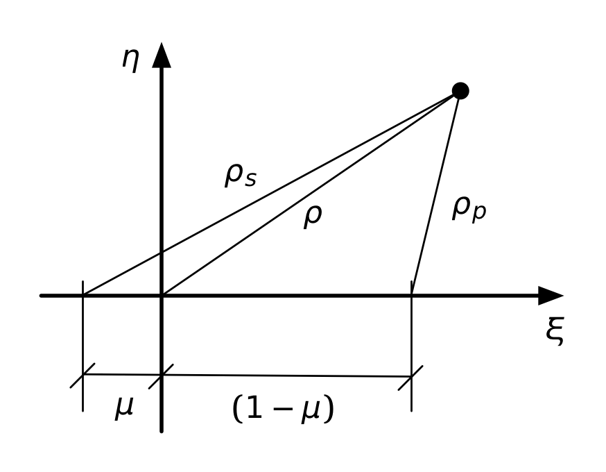
Using , , and makes for a compact expression, but it isn’t convenient for plotting, which is what I want to do to help find the stationary points3 of . We need to express in terms of and , which we get from the Pythagorean formulas
So we end up with this,
which is a nasty mess, but we have computers to keep track of everything, so there’s no need to worry about losing terms.
Plotting the potential energy
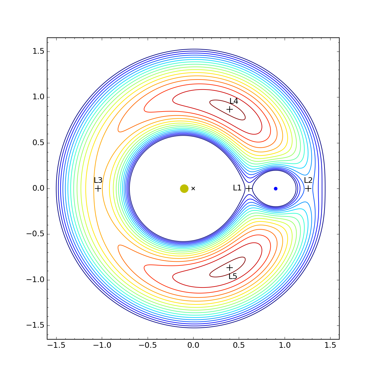
Here’s the contour plot of as a function of (abscissa) and (ordinate). I’m plotting it for , because that’s a value that allows us to see all the Lagrange points. (For the Earth-Sun system, , which would put L1 and L2 so close to the Earth itself we wouldn’t be able to distinguish them at this scale.)
The dirty yellow dot is the sun, the blue dot is the planet, the × is the barycenter, and the various crosses are the stationary points of . You can click on the plot to see a bigger version.
The contour lines represent equal spacing in the value of . They range from dark blue for the lowest points to dark red for the highest. We see that L1, L2, and L3 are colinear with the sun and planet and are at saddle points. L4 and L5 are at local maxima. The coordinates of the points, which I calculated using techniques we’ll get into later, are as follows:
| Point | ||
|---|---|---|
| L1 | 0.609 | 0.000 |
| L2 | 1.260 | 0.000 |
| L3 | -1.042 | 0.000 |
| L4 | 0.400 | 0.866 |
| L5 | 0.400 | -0.866 |
The coordinates of L1, L2, and L3 pretty much have to be calculated numerically. There’s no nice closed-form solution to get those values. But there is a simple, non-computational way to get the positions of L4 and L5, and the clue is in the values you see in the table.
That 0.866 you see for the value is the sine of 60°, and the 0.400 is exactly 0.1 less than the cosine of 60°. Remember that the sun is 0.1 to the left of the origin and the planet is 0.9 to the right of the origin. Putting this all together, we see that L4 is at the intersection of a 60° line up and out from the sun and a 60° line up and back from the planet. Similarly for L5, except that the lines are 60° down instead of up. Which means that L4 and L5 form equilateral triangles with the sun and the planet.
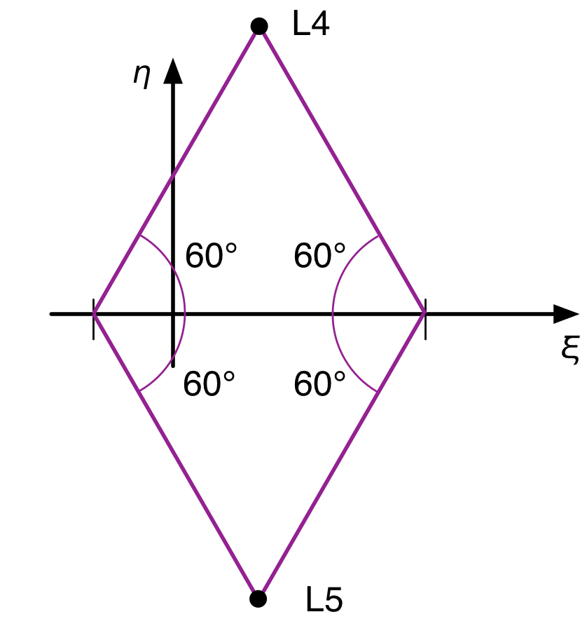
This is not a coincidence that just happens to work out when . It’s true regardless of the mass distribution between the sun and the planet. In the next section, we’ll prove that, but the math gets messy. If you want to just take it on faith, skip this next section.
Equilateral triangle diversion
For the fearless few, we’re going to use that trick I found in Richard Fitzpatrick’s book. There’s nothing especially hard in this; it’s just a lot of tedious algebra, and I’m going to show all the steps. Textbooks usually don’t for reasons of space, but there’s a lot of space on a web page.
Recall that
If we multiply the first of these by and second by and add them together, we get (after some cancellation)
Therefore
We can substitute this into the compact expression for to get
or, after rearranging
Equations for the stationary points
What good is this? Well, although it may not seem like it, it actually makes it a little easier to take the partial derivatives of with respect to and in order to find the stationary points. We’ll use the chain rule to do it:
The partial derviatives with respect to and are simple:
The easy way to get the partials of and with respect to and is to take the total differentials of the expressions for and :
Dividing the top equation by and the bottom by gives us
which means
Now we have all the pieces needed to build the equations for the stationary points:
Simplifying a bit we get
Solving the equations
The second equation is the key. First, we can factor out the :
This means that either
which is what leads us to L1, L2, and L3 (we’ll get to that later), or
Let’s explore this condition. We’ll move the terms that don’t involve or to the other side of the equation.
An obvious solution to this equation is , which will work for all values of . What we don’t know, though, is whether that’s the only solution for . To see if it is, we have to combine this result with the first stationary equation.
Let’s start by solving for . We can multiply through by to get rid of the fractions:
And then solve for :
We plug this into the first stationary equation to get
which simplifies first to
and then to
Once again, we can factor out a common term and simplify:
With this, we can say either
or
But the second of these is impossible because the and terms cancel, leaving . So the only solution for is
and therefore , which means , confirming our guess about the equilateral triangle solution for L4 and L5.
Determining the colinear positions
OK, now that we’ve confirmed the equilateral triangle postions for L4 and L5, let’s explore the colinear positions, L1, L2, and L3.
The two equations that must be satisfied for every Lagrange point are
(If you’re wondering where these equations came from, it’s because you skipped over the previous section. The path to enlightenment is not easy, grasshopper.)
An obvious condition that solves the second equation is . That’s the value of for L1, L2, and L3. All we need to do then is pull three solutions for out of the first equation. We’ll refer to this layout of the points to specialize the equation for each of the points:
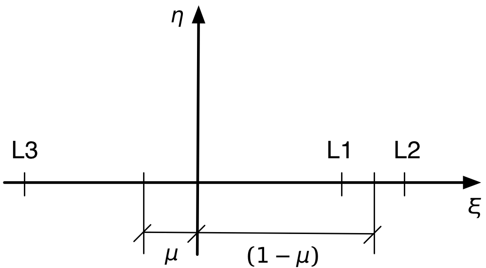
L1
Let’s start with L1, where
For very small values of , will also be small, so it’s convenient to put the whole equation in terms of :
Expanding and collecting terms gives
or
Most numerical equation solving routines will have no trouble with this equation, but as I said earlier, there is no simple closed-form solution for it. We can, however, take advantage of the fact that is relatively small when is very small to get a closed form approximate solution:
or
Notice that and are at different levels of “small.” The cube/cube root relationship means that is much smaller than .
For , a numerical solution of the exact expression gives which corresponds to as given in the table above. The approximate solution is , which is pretty far off, mainly because just isn’t small enough.
L2
The determination of L2 follows the same pattern. For this position, with the point beyond the planet,
so
After expanding, collecting, and rearranging as we did above, we get
As with L1, this can be solved numerically without much trouble, but there is a decent closed-form approximation for small and . It’s the same as the approximation for L1:
or
This puts the L2 position about as far outside the planet’s orbit as L1 is inside the planet’s orbit.
For , a numerical solution of the exact expression gives which corresponds to as given in the table above. The approximate solution is , which again is pretty far off.
L3
Finally, we have L3, where we have to be careful with the signs. Because they’re distances, and are positive, but the coordinate is negative.
In this case, we’ll write the first stationary equation in terms of .
In this case, is going to be close to 1, so we can introduce a small value, , such that . That turns the stationary equation into
which looks like a real mess, but as before we expand, collect, and rearrange to get
Ignoring the higher-order terms in , we get the approximation
In this case, and are at about the same order of “small.”
Using this approximation, the coordinate is
For , a numerical solution of the exact expression gives which corresponds to as given in the table above. The approximate solution is . The percent error in this approximation for is comparable to that of the earlier approximations for .
The Sun-Earth Lagrange points
As mentioned earlier, for the Sun-Earth system. With such a small value of , the approximations developed above should be pretty accurate. Let’s see.
- For L1, a numerical solution of the exact equation gives , while the approximate solution is .
- For L2, a numerical solution of the exact equation gives , while the approximate solution is .
- For L3, both the numerical solution of the exact equation and the approximate solution are . You have to go four more decimal places to see a difference.
As expected, the approximations are quite good. Probably not good enough for NASA, but good enough for a blog post.
The real value of the approximate formulas is not for computation, it’s for insight. By seeing how and scale with , we get a sense of how the positions of the colinear Lagrange points change with changing mass distributions.
Stability
It’s often said that L4 and L5 are the stable Lagrange points. This seems wrong, because those points are at local maxima of the potential energy, not local minima, and stability is associated with minima. My understanding is that the stability comes from Coriolis forces, which tend to keep objects in orbit around L4 and L5. We didn’t include a Coriolis term in our potential energy expression because our analysis was designed to find places where the satellites would be stationary in our rotating frame of reference. Coriolis forces arise only when a body is moving relative to the rotating frame.
I may look into redoing the analysis with a Coriolis term. Check back in another year.
Update 08/18/2016 8:23 AM
The Trojan asteroids are clustered around the L4 and L5 positions of the Sun-Jupiter system. They got a mention from Jason Snell and Stephen Hackett on this week’s episode of their Liftoff podcast, which I just listened to this morning. The plan of the proposed Lucy space mission is to visit five of the Trojan satellites.
A tip from Jeff Youngstrom on Twitter led me to this remarkable page by Petr Scheirich, which has a wealth of graphics related to comets and asteroids, including this animation of the Trojan (green) and Hilda (red) groups as viewed in a reference frame that rotates with Jupiter.
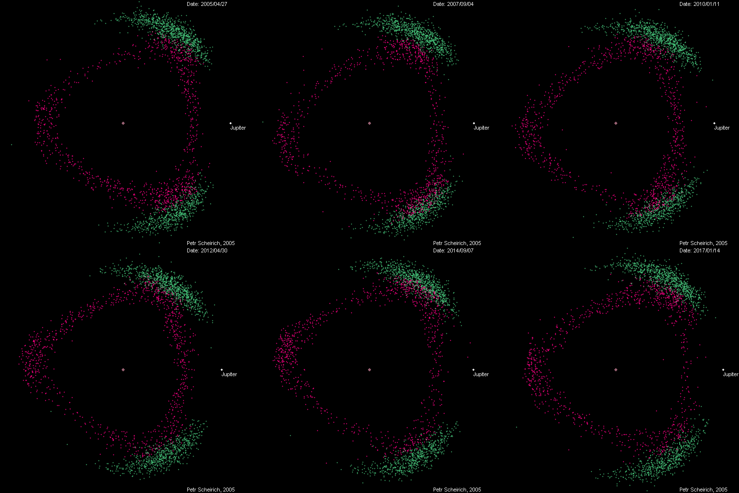
The animation covers, I believe, one Jovian year. The in-and-out movement of Jupiter represents its elliptical orbit from perihelion to aphelion, and you can track the orbits of at least some of the green dots around the L4 and L5 positions.
-
Although we tend to be most interested in the Sun-Earth Lagrange points, there are similar points for every sun-planet combination and for every planet-moon combination, too. ↩
-
And it’s not a coincidence that it looks like a kinetic energy term with the sign changed. D’Alembert strikes again! ↩
-
Stationary points are where the function is at a local maximum, minimum, or saddle point. They’re the points where the slopes of the function’s surface are zero. ↩

