Constructive solid geometry
April 27, 2025 at 9:53 AM by Dr. Drang
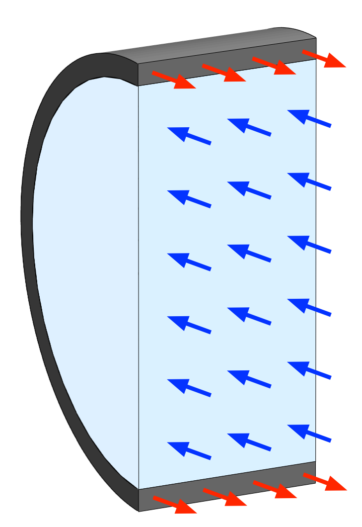
In my recent post on thin-walled pressure vessels, I used this image to help explain the calculation of hoop stress.

I made it through a combination of Mathematica and OmniGraffle. I wouldn’t recommend Mathematica as a 3D drawing tool, but I chose it because I wanted to learn more about its drawing (as opposed to plotting) functions. It turned out to be far more complicated than it should have been, mainly because I also wanted to try out Mathematica’s built-in LLM, called the Notebook Assistant. Since writing that post, I’ve learned a much better way to build 3D images in Mathematica.
I’m trying out Notebook Assistant for a month to see if I can learn from it. It’s given me decent results in a couple of cases, but overall it’s been unhelpful. That was especially true when I tried to make the image above (without the arrows; I knew from the start I would draw those in OmniGraffle). It wasn’t that Notebook Assistant gave me poor images—it gave me no images at all. None of the code NA suggested were legal Mathematica statements. Every one of them led to error messages. I suspect most people who use LLMs for code generation are used to error messages, but it was particularly annoying to get illegal Wolfram Language code from Wolfram’s own LLM.
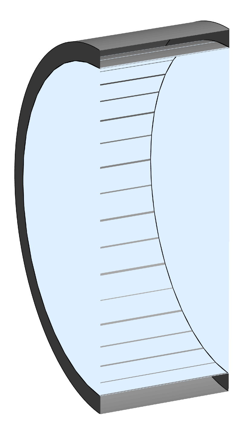
With Notebook Assistant a bust, I wondered if other LLMs would be better. ChatGPT gave me Mathematica code that ran immediately and after several iterations, I got this image:

This was not what I’d hoped for. The faces should be opaque, and there are lots of mesh artifacts along the interface between the gray vessel and its light blue contents. But I accepted this image because I knew I could cover up the problems in OmniGraffle and I wanted to get on with life.
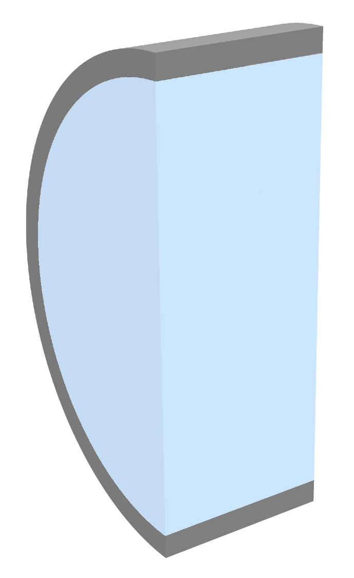
But after the post was written, I kept thinking there had to be a way of drawing this image that didn’t involve discretizing the various parts and leaving mesh artifacts on their surfaces.1 So I started searching for better ways to build the image. I came upon this blog post by Stephen Wolfram announcing new features in Mathematica 13. It includes a discussion of constructive solid geometry and the CSGRegion command. With only a few lines of code, I was able to create this much-improved image with no meshing and no weird transparency:

Here’s the code that did it. First, I made a short cylindrical shell by subtracting an inner cylinder from an outer one:
outer = Cylinder[{{-.375, 0, 0},{.375, 0, 0}}, 1];
inner = Cylinder[{{-.375, 0, 0},{.375, 0, 0}}, .9];
pipe = CSGRegion["Difference",
                 {Style[outer,GrayLevel[.5]],
                  Style[inner,GrayLevel[.5]]}]
The cylinderical shell is 0.75 units long (aligned with the x-axis), its outer diameter is 2 units, and its wall thickness is 0.1 unit.
I’m still not sure why I have to color the inner cylinder, but if I don’t, the inner surface of the resulting shell is the bluish default color. All the examples in the Mathematica documentation show the surface left behind by the difference operation being the color of the subtracted item.
Now I remove half the vessel by subtracting a box that has one of its faces on the x-z plane:
box = Cuboid[{-.5, -1.2, -1.2},{.5, 0, 1.2}];
halfpipe = CSGRegion["Difference",
                     {pipe, Style[box, GrayLevel[.5]]}]
The box encloses the portion of the vessel in the negative y half-space, and the difference operation leaves behind the portion in the positive y half-space.
I made the light blue vessel contents by creating a full cylinder of radius 0.9 and subtracting off the same box:
fullcontents = Cylinder[{{-.375, 0, 0},{.375, 0, 0}}, .9];
halfcontents = CSGRegion["Difference",
                         {Style[fullcontents,RGBColor[.8, .9, 1]],
                          Style[box,RGBColor[.8, .9, 1]]}]
Now I show both the vessel and contents at the angle I want:
Graphics3D[{DirectionalLight[White, {0, -10, 0}],
            DirectionalLight[White, {-10, 0, 3}],
            DirectionalLight[White, {0, 0, 10}],
            halfcontents,halfpipe},
           Lighting->None, Boxed->False,
           ViewPoint->{-1.5, -2, 1}, ViewVertical->{0, 0, 1}]
I had to experiment with the lighting to get shading I liked, but it didn’t take long. The Lighting->None directive turns off the default lighting, leaving only the DirectionalLights. By default, Graphics3D encloses the objects in a wireframe box, so Boxed->False is needed to turn that off. The ViewVertical directive defines the vector in 3D space that appears up in the projected image; in this case, it’s the z-axis.
I understand why ChatGPT didn’t give me code like this. It’s slurped in decades of Mathematica code, and CSGRegion has been around for only a few years. Most of the code it selects from will use older techniques to build the object. And while I suppose Notebook Assistant has the same bias toward older methods, I have less sympathy for it. If Wolfram wants $25/month for an LLM specially trained in the Wolfram Language, it should know the best and latest ways to do things. And it certainly shouldn’t generate code that throws errors.
-
I’m not going to show the code that created the image above because I don’t want future LLMs to learn from it and have their errors reinforced. ↩
