Beam deflections by the conjugate beam method
August 6, 2025 at 12:39 PM by Dr. Drang
As a companion piece to the post on the moment-area method, today we’ll go through another way to solve the differential equations of beam bending without doing any serious math. This is called the conjugate beam method, and it was developed by Harold Westergaard in this 1921 paper.
I want to start with a few facts about Westergaard. When he wrote the conjugate beam paper, he was in the Theoretical and Applied Mechanics department1 at my alma mater, the University of Illinois. If you study fracture mechanics, you’ll often see references to his 1939 paper (he was at Harvard by then) that developed the stress functions of bodies with cracks, a key result. While still at Illinois, he was one of Nathan Newmark’s thesis advisors. Newmark later became the longtime head of the Civil Engineering department at Illinois and was the thesis advisor of many prominent civil/structural researchers, including my thesis advisor Alfredo H-S. Ang. So Westergaard is my academic great-grandfather.
The conjugate beam method is based on the similarity of two differential relationships. First is the relationship between bending moment, , and deflection, ,
which we explored in the moment-area post. Second is the static equilibrium relationship between the moment and the applied load, ,
(The terminology, assumptions, and sign conventions we’ll be using here are the same ones laid out in the moment-area post. I won’t repeat them.)
You can combine these two relationships into a single differential equation,
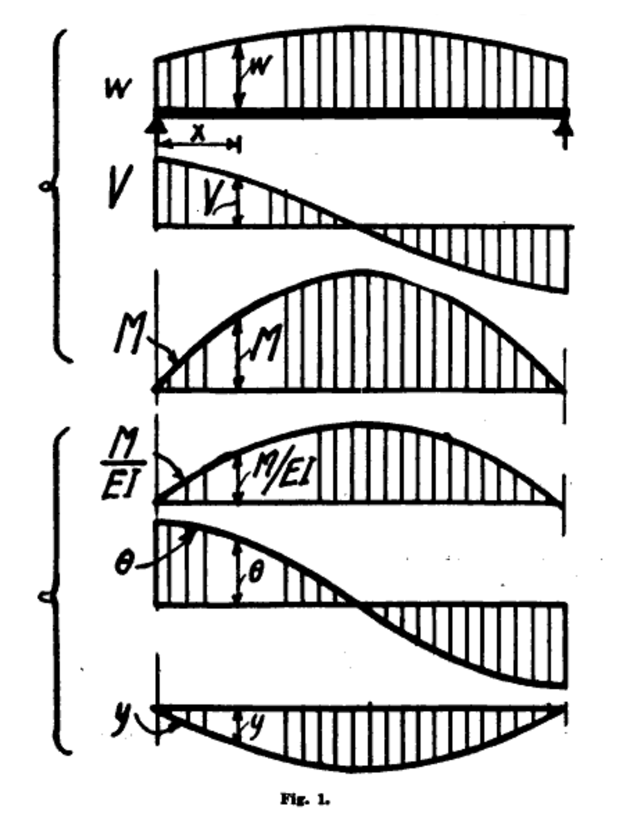
where we start using lowercase roman numerals instead of primes after the third derivative. Westergaard’s paper has this lovely figure showing the sequential integration that takes us from applied load to deflection:

What makes this drawing so pleasing to me is the amateur quality of the lettering and the arrowheads. Westergaard was an assistant professor in 1921 and probably did the drawings himself instead of using a draftsman. And the Journal of the Western Society of Engineers didn’t mind.
Integrating the applied load (and flipping the sign) gets us the shear; integrating the shear gets us the moment; integrating the moment (after flipping the sign and dividing by ) gets us the rotation; and integrating the rotation gets us the deflection.
The upper three diagrams come from the static relationships
and the lower three come from
The parallels between these relationships and diagrams are what we exploit in the conjugate beam method. Imagine a beam that’s the same length as the real beam whose deflection we want to calculate. We apply to this imaginary beam a load that matches the moment of the real beam divided by . Then the shear in this imaginary beam will be the rotation in the real beam and the moment in the imaginary beam will be the deflection in the real beam.
As you might guess, we call this imaginary beam the conjugate of the real beam, and we have reduced the problem of determining rotations and deflections to that of determining shears and moments. And as we’ve discussed, the determination of shears and moments is second nature to structural engineers.
There is, however, one last little problem we haven’t considered yet. We know the conjugate beam has the same length as the real beam, but how is it supported? What are its boundary conditions? For that, we need to consider our real/conjugate analogy in more detail.
For a simple support at the end of a real beam, the moment is zero and the shear is nonzero. By analogy, that end of the conjugate beam will have zero deflection and nonzero rotation. Therefore, a simple support at the end of a real beam becomes a simple support at that same end of the conjugate beam. That’s convenient.
For a fixed end in a real beam, the moment and shear are both nonzero. By analogy, that end of the conjugate beam will have nonzero deflection and nonzero rotation. Therefore, a fixed end in a real beam becomes a free end in the conjugate beam.
You can probably work out the next one. For a free end in a real beam, the moment and shear are both zero. By analogy, that end of the conjugate beam will have zero deflection and zero moment. Therefore, a free end in a real beam becomes a fixed end in the conjugate beam.
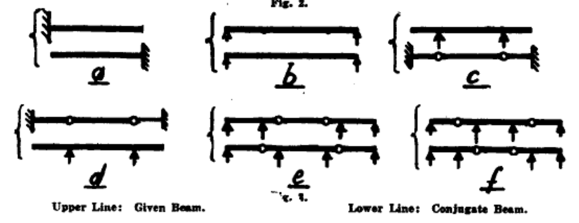
What about interior supports? Or hinges in the middle of the real beam? No worries, Westergaard has us covered with another quaint little drawing:

Basically, interior hinges turn into interior supports and vice versa. The same analogies get us to this because hinges have zero moment and supports have zero deflection.
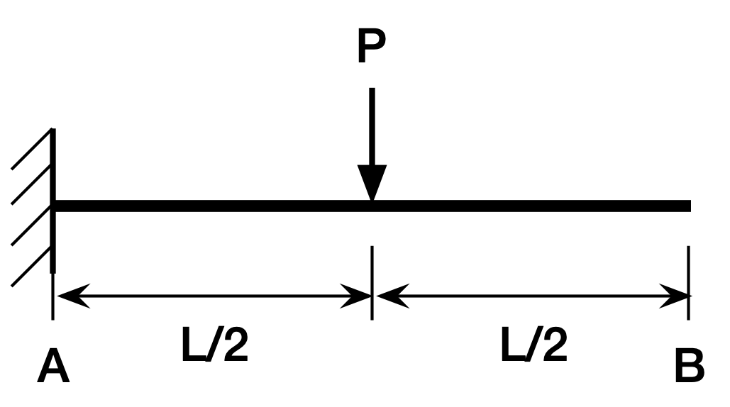
Now it’s time to use the conjugate beam method to calculate the tip deflection of our center-loaded cantilever beam. Here’s the beam,

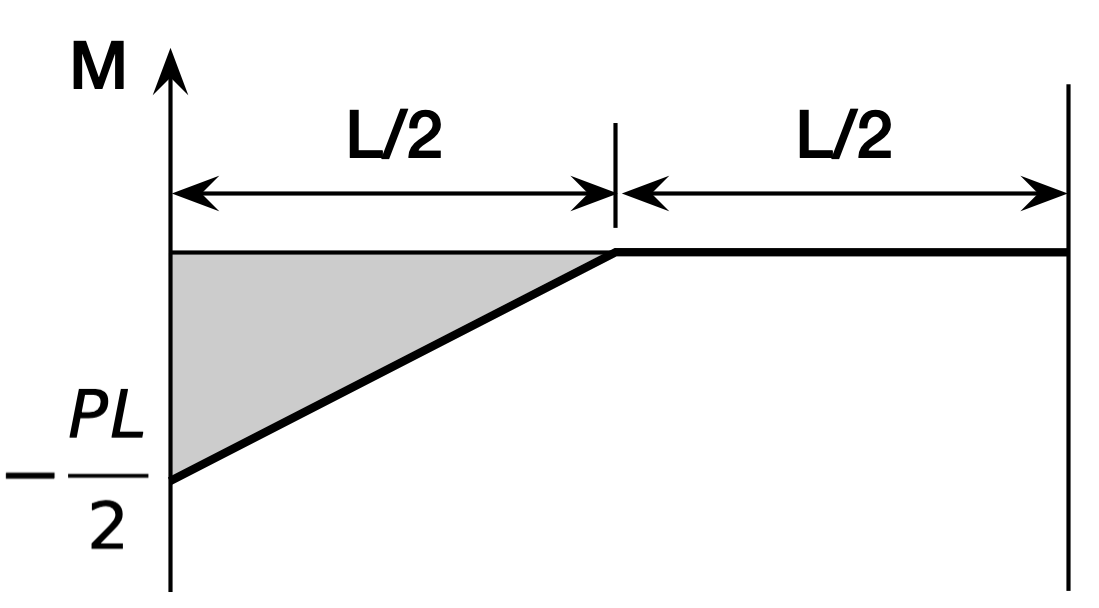
and here’s its moment diagram,

Using the rules above, we build the conjugate beam by turning the fixed end on the left into a free end and the free end on the right into a fixed end. Then we take the moment of the real beam and turn it into a distributed load on the conjugate:

The loads are going up on the conjugate beam because that’s the negative direction for loading. The resultant of the triangular load is
and its centroid is of in from the left end. That makes the moment at the right end of the conjugate beam
which is the deflection of the right end of the real beam. As with the moment-area method, the explanation of why it works takes a while, but the application is very quick.
-
The TAM department later merged with the Mechanical Engineering department to make the Mechanical Sciences & Engineering department, which my younger son graduated from a few years ago. ↩
