Beam deflections by the moment-area method
July 31, 2025 at 10:53 PM by Dr. Drang
My last few posts have involved the solution of differential equations. Structural engineers tend to avoid using the solution techniques taught in math class, partly because we’re not that good at math and partly because people who were good at math figured out ways for us to get solutions with only some simple geometric calculations. One of those ways is the moment-area method for calculating beam deflections. It’s a way of solving differential equations without solving differential equations.
Here’s a beam with a distributed load.
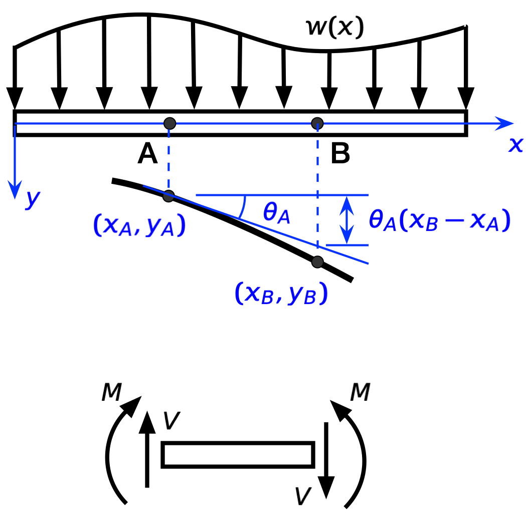
Under the beam, the thick black curve is the deflected shape of the beam’s centerline, and under that is a chunk of the beam showing the internal stress resultants; is the shear force, and is the bending moment. For the sign convention I’m using—which is the common convention used in structural engineering—everything is shown in the positive direction:
- The position along the beam, , is positive to the right.
- The deflection of the beam, , is positive downward.
- The distributed load, , is positive downward.
- The rotation or slope of the beam, , is positive clockwise.
- The curvature of the beam, , is positive when the curve is concave down.
- The shear is positive when it’s up on the left end of a free-body diagram or down on the right end of a free-body diagram.
- The moment is positive when it’s clockwise on the left end of a free-body diagram or counter-clockwise on the right end of a free-body diagram.
A few things to note:
I’m using primes to indicate derivatives with respect to , i.e.,
and
All deflections and angles will be small, so the slope and the angle taken as the same:
This also means that the curvature is taken as the second derivative of the deflection:
The beam is made of a linearly elastic material with Young’s modulus .
- The beam’s cross-section is constant with principal moment of inertia , the axis of which is perpendicular to . This insures that the beam’s bending stays in the plane.
These last three items are standard assumptions. You can relax the last two to allow for beams where and change along the length of the beam, but I won’t be dealing with that here.
A key relationship in the analysis of beams is that curvature and bending moment are proportional:
This is the differential equation that ChatGPT and Claude tried to solve in the posts I published last week.
A lot of a structural engineer’s education is spent learning how to draw moment diagrams—a plot of as a function of —quickly and accurately. This is because the stresses in a beam are determined primarily by the bending moment in the beam. And if you have the moment diagram, you also have the curvature diagram; you only need to flip the sign and divide by .
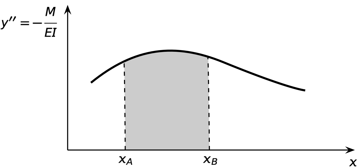
And it turns out there are some simple geometric calculations you can use to determine rotations and deflections from the curvature diagram. These calculations make up the two theorems of the moment-area method.
The first theorem is pretty simple. If we take the shaded area under the curvature curve between and , the result will be the difference in rotation between points A and B:
This is most useful if the rotation at A or B is zero, which you can often ensure by choosing one of the points carefully, but there are ways to combine it with other knowledge even when neither rotation is zero.
The second moment-area theorem is more complicated. Let’s start by looking at this integral:
This is the moment of the shaded area about point B, and we can do some interesting things with it. First, we’ll split it into two parts:
The first of these integrals is straightforward:
For the second, we’ll use integration by parts with
which means
So
which works out to
Putting the two parts together, we get some cancelation and
This form is more useful:
Looking back at our deflection drawing,

we see that the moment of the shaded area about B (that’s the integral) is the downward distance of point B from the tangent line drawn through point A.
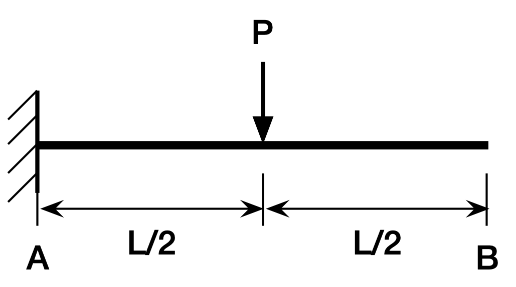
This may seem like a mess, but it tends to be very easy to use in practice. Let’s use it to solve the cantilever beam problem that ChatGPT and Claude had trouble explaining.
The moment diagram is
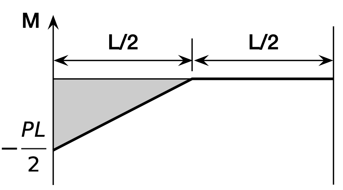
We’ll put point A at the fixed end and B at the free end. That means and . Therefore, the moment of the shaded area about point B (after flipping the sign and dividing by ) will be the deflection at B. That works out to
which is the right answer. The reason this is so easy is that you know the area of a right triangle is one-half the product of the two legs and that its centroid is two-thirds of the way from the pointy end. Multiply the area (in the first pair of parentheses) by the distance its centroid is from point B (in the second pair of parentheses) and you’re done.
In practical problems, moment diagrams tend to be combinations of straight lines and parabolas, and once you know their areas and centroids, the moment-area calculations become second nature. A few years ago, I wrote a post with this diagram showing the areas and centroids of parabolic regions:
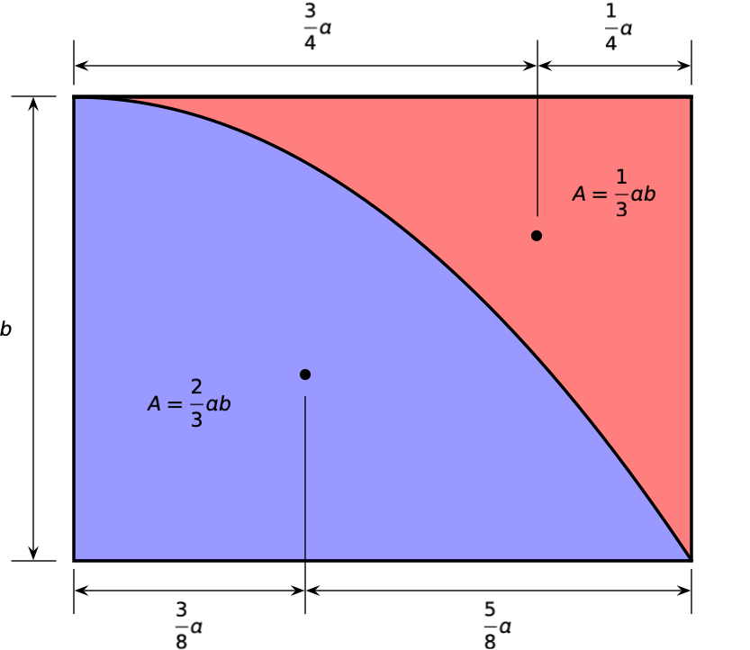
At the end of that post, I said I felt compelled to write a followup on the moment-area method. Obviously, the compulsion wasn’t that strong, as it took me three years to do it. But here it is.
