Moment diagrams for continuous beams
April 6, 2024 at 1:21 PM by Dr. Drang
As promised last time, we’ll now work out the solution for this three-span continuous beam with a uniform distributed load.
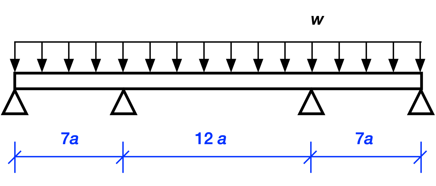
Because there are four unknown reaction forces at the supports and only two equations of statics1, we can’t solve for the reactions by statics along. This means the structure is statically indeterminate. And because there are two more unknowns than equations, we say that it has two degrees of indeterminacy.
But wait, can’t we use symmetry in addition to statics to solve for the reactions? After all, symmetry tells us that the two interior support reactions must be equal and the two exterior support reactions must also be equal.
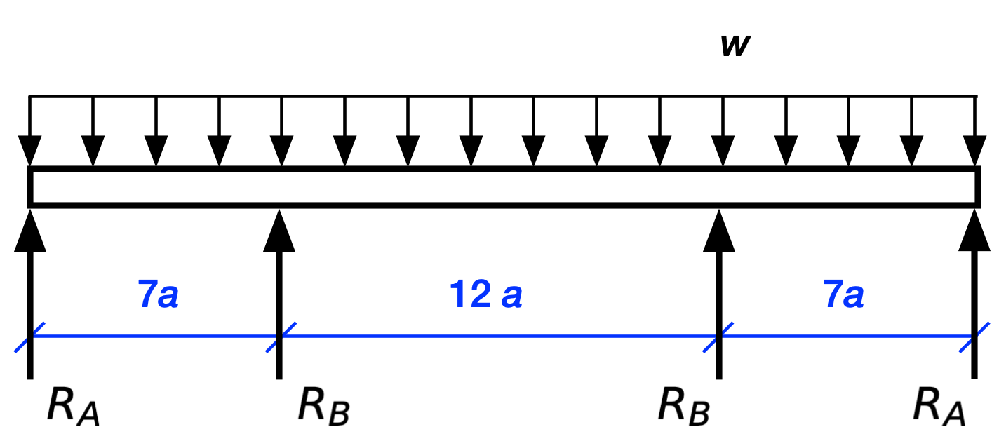
Let’s see what we can do with this. The equations of equilibrium for vertical loading and the moment about the left support are
These may look like two equations, but they really aren’t. After some algebra, they become
which are the same equation. So our two equations of statics aren’t independent and we really have one equation with two unknowns. That’s only one degree of indeterminacy, which is an improvement, but still isn’t enough to solve the problem through statics alone. And if you think you can get an independent equation by taking moments about another point, go ahead and try. I’ll be here when you come back.
To solve this problem—and to solve indeterminate problems in general—we have to account for the stiffness of the structure. There are many ways of doing this. If it were 1980 and I were still an undergraduate, I’d probably use moment distribution, because that was the standard way to do problems by hand back then. I suspect that most engineers today would use the finite element method. That’s the most practical solution, but letting your computer do all the work is no fun.
The fun way is to take advantage of symmetry and use Castigliano’s Second Theorem. Alberto Castigliano was a 19th Century Italian engineer whose 1873 thesis, Intorno ai sistemi elastici or Regarding elastic systems2 included his theorems and their proofs. You probably haven’t heard of Castigliano—he’s no Newton or Euler or Bernoulli—but there aren’t many dissertations whose findings are still being taught a century and a half later.
Castigliano’s Second Theorem is based on work and energy principles. Say we have a linearly elastic structure—that’s one where the deflection is a linear function of the loading and the structure springs back when the loads are removed. If we have a set of concentrated external loads acting on the structure, , we can express the strain energy, , as a function of those loads. Then the deflections, , of the points of load application in the directions of the , can be determining from the partial derivatives of the strain energy with respect to the loads:
The strain energy in a beam can be written in several ways. When solving problems by Castigliano’s Second Theorem, we write it in terms of the bending moment like this:
That’s the theory. Now let’s talk about the practice.
The strategy when using Castigliano’s Second Theorem to solve a statically indeterminate problem is the following:
- Remove the “extra” supports, i.e., the ones that are making the structure indeterminate. Since any of the supports could be considered extra, you have some freedom here. With experience, you’ll choose supports that make your calculations easy.
- Replace the supports with the forces (as yet unknown) that act at those supports
- Write out an expression for the strain energy in terms of the replacement forces.
- Take the partial derivatives of the strain energy with respect to those forces.
Set the partial derivatives to zero because the displacements at the supports that were removed are zero, i.e.,
- Solve the equations in Step 5 for the replacement forces.
The procedure is easier to show than it is to tell. Here’s our structure with the interior supports replaced by forces.
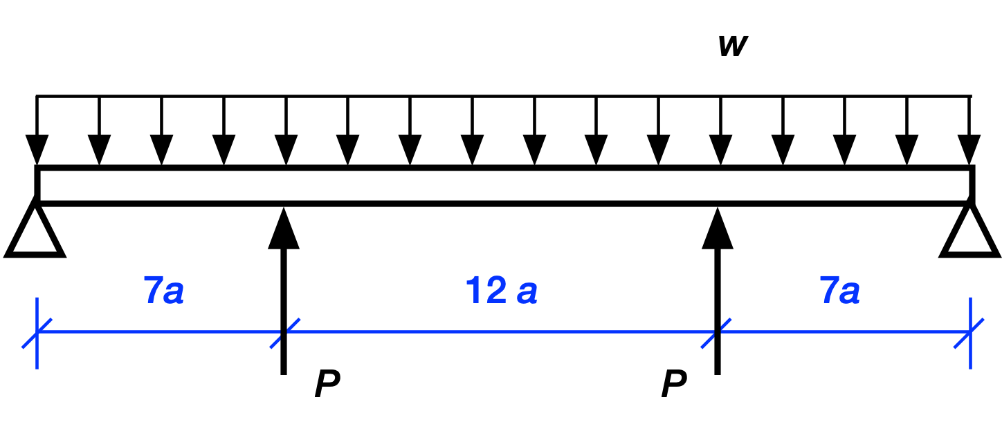
The two interior concentrated loads are equal because of symmetry. Since this is a linearly elastic structure, we can use superposition to analyze this complex loading. That is, we can break the complex loading into two or more simpler loading conditions that are easy to solve. After solving for the simpler loads, we add them together to get the solution for the complex loading. In graphical language, we do this:
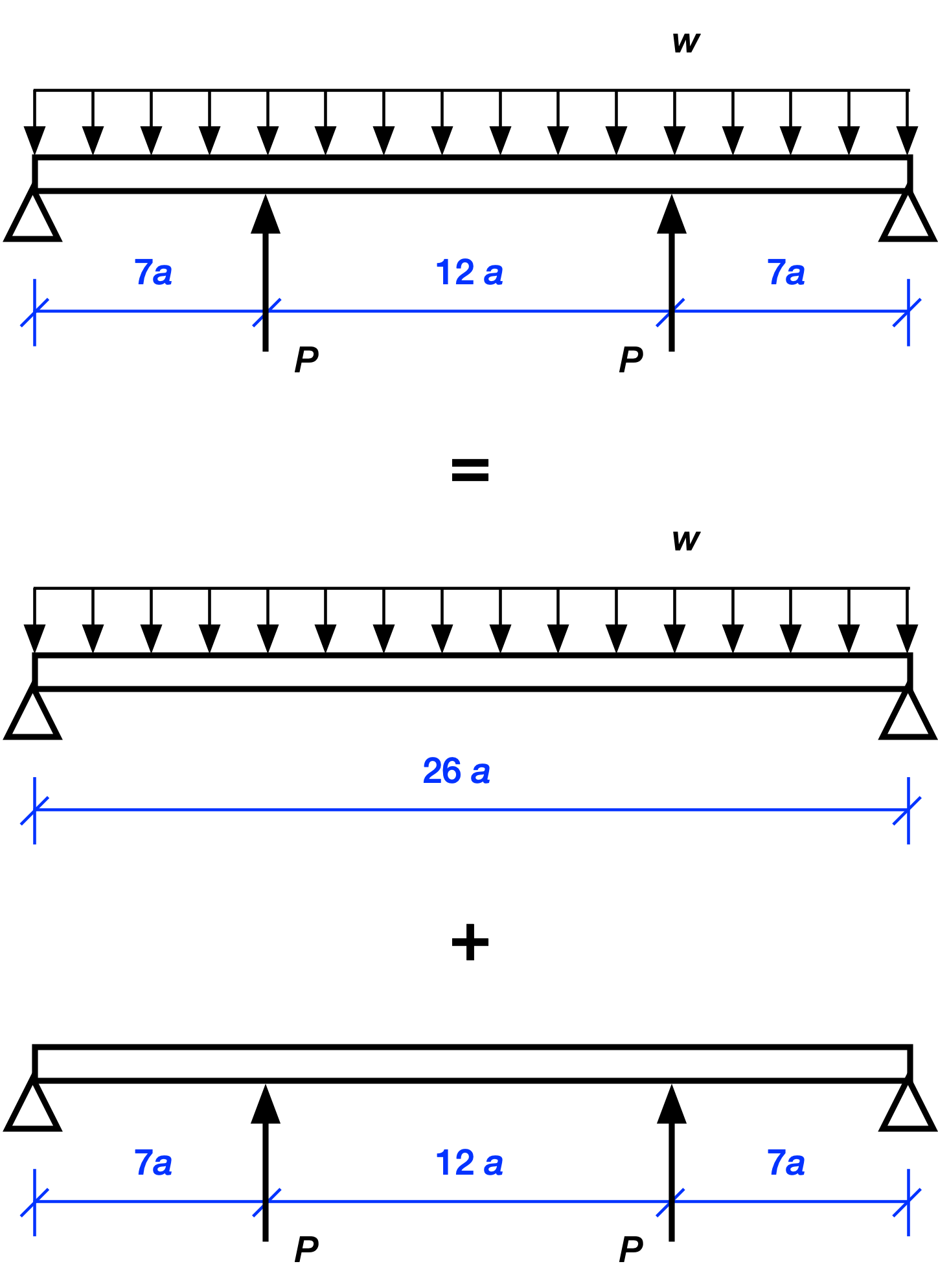
Let’s start with the reactions at the ends. Clearly, the upward reaction forces at the end supports are
where the first term is what the reaction would be if only the uniformly distributed load were acting and the second term is what the reaction would be if only the two interior point loads were acting. The sign of the term is negative because the reactions from the s alone would be downward.
The moment diagrams for two simpler load conditions are this for the uniformly distributed load
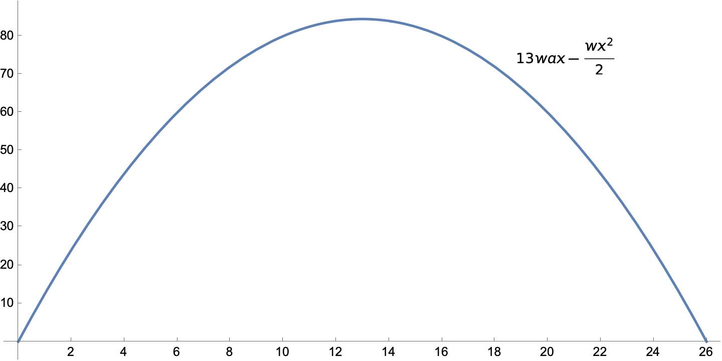
and this for the two concentrated loads.
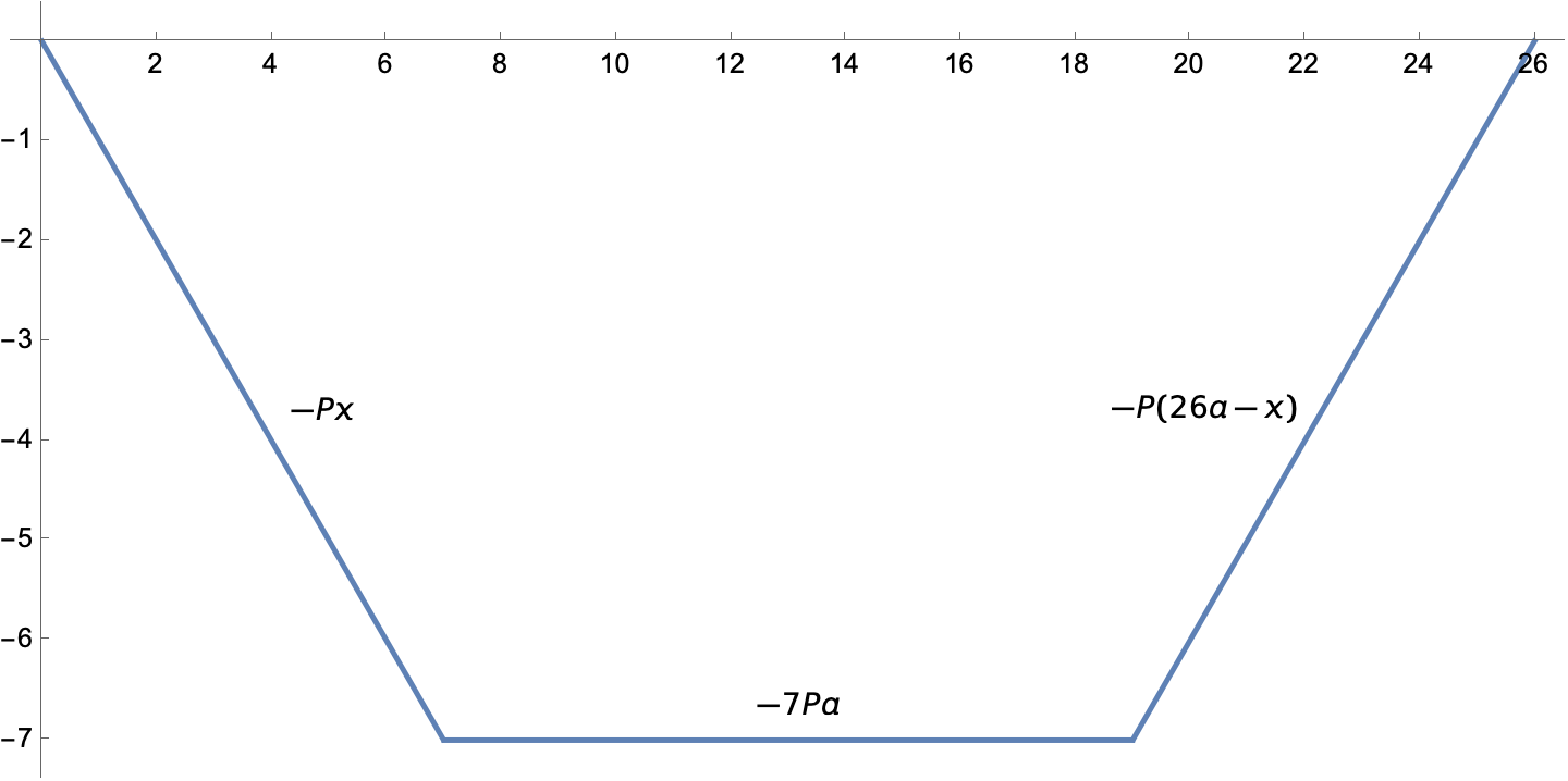
Concentrated loads put kinks in the moment diagram.
When we add the two moments together, we get this piecewise expression:
For each piece, the first two terms are due to the distributed load and the last term is due to the concentrated loads.
With the bending moment defined in terms of the unknown, , we can use the equation above to get the strain energy. I’m not going to pretend I did it by hand; here’s the Mathematica code,
M1 = 13*w*a*x - w*x^2/2 - P*x;

M2 = 13*w*a*x - w*x^2/2 - 7*a*P;

M3 = 13*w*a*x - w*x^2/2 - (26 a - x)*P;

U = Integrate[M1^2/(2*EI), {x, 0, 7*a}] +
    Integrate[M2^2/(2*EI), {x, 7*a, 19*a}] +
    Integrate[M3^2/(2*EI), {x, 19*a, 26*a}]
which gives us a strain energy of
When you give Mathematica integer input, it gives you integer or rational output, hence the large numbers in the numerators.
Taking the partial derivative of this with respect to and setting it to zero,
soln = Solve[D[U, P] == 0, P]
gives us
We plug this back into the expression for and get
To plot the moment diagram in Mathematica, we do what we did last time: divide the moment expressions by and introduce a nondimensional length variable, . The code is
m1 = M1/(w*a^2) /. {soln[[1]][[1]], x -> u*a};

m1 = Simplify[m1];

m2 = M2/(w*a^2) /. {soln[[1]][[1]], x -> u*a};

m2 = Simplify[m2];

m3 = M3/(w*a^2) /. {soln[[1]][[1]], x -> u*a};

m3 = Simplify[m3];

Plot[Piecewise[{{m1, u <= 7}, {m2, 7 < u <= 19}, {m3, u > 19}}], {u, 0, 26},
  ImageSize -> Large, PlotStyle -> Thick,
  Ticks -> {Table[t, {t, 0, 26, 2}], Table[t, {t, -12, 10, 2}]}]
where again the Piecewise function lets us split the function being plotted into pieces. Note also that we’re using the soln expression that came from the solution for to plug that into the various expressions.
The resulting plot is
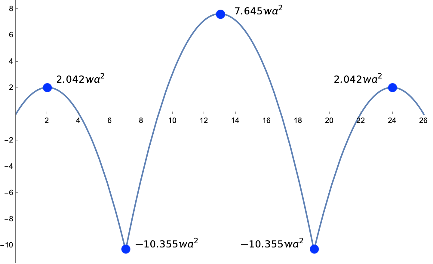
except that I added the annotations in Preview.
I’ll spare you the work involved in making the third moment diagram in the Francis Scott Key Bridge post, the one for a beam with the left interior support missing. The process is the same as what we just went through.
I should mention, though, that although this seems complicated when every step is explained, most structural engineers would be able to whip through this analysis quickly. They wouldn’t have wasted time showing that symmetry doesn’t make this problem statically determinate. They would know immediately to use superposition. And they’d draw the two moment diagrams for the simpler problems as fast as their pencil could move. That’s how expertise works.
-
Recall that the horizontal equilibrium equation gives us no information because there are no horizontal forces. ↩
-
Google Translate told me the English translation was Around elastic systems, which seemed off. I thought Google was taking “itorno” too literally; it should be something like “on” or “about.” So I asked Federico Viticci what he thought, and he gave me “regarding” as a good translation of an older Italian usage. Thanks, Federico! ↩

